192866 Issue 4 - Reel to Reel Manual LoRes - 第25页
USER SETUP Chapter Issue 3, August 14 Reel to Reel Manual 2.1 CHAPTER 2 USER SETUP Overview This chapter outlines a product changeove r and setting up on the reel to reel machine. This must be treated as a gu i de only ,…

TECHNICAL REFERENCE
REPLACEMENT PROCEDURES
1.14 Reel to Reel Manual Chapter Issue 1, Apr 15
4. Fit one end of the new belt in the belt clamp on the right hand side of the
inner transport vacuum plate ensuring the correct amount of belt is protrud-
ing out of the bottom of the clamp, see table below:
5. Tighten the belt clamp.
6. Feed the belt over the top of the belt pulley on the right hand side of the
transport mechanism.
7. Continue to feed the belt under the inner transport vacuum plate and feed
the belt over the left pulley.
8. Fit the end of the belt in the belt clamp on the left hand side of the inner
transport vacuum plate ensuring the correct amount of belt is protruding out
of the bottom of the clamp, see table below:
9. Tighten the belt clamp.
10. Check the other two belts for damage.
Belt Position Dimension
Front Belt 25mm below the clamp
Middle Belt 20mm below the clamp
Rear Belt 15mm below the clamp
Belt Position Dimension
Front Belt 25mm below the clamp
Middle Belt 20mm below the clamp
Rear Belt 15mm below the clamp
USER
SETUP
Chapter Issue 3, August 14 Reel to Reel Manual 2.1
CHAPTER 2 USER
SETUP
Overview This chapter outlines a product changeover and setting up on the reel to reel
machine. This must be treated as a guide only, as each reel to reel application
is customer specific and unique.
Product Changeover
1. Ensure there is no screen fitted to the machine.
2. Select Setup Product.
3. Select Load Product.
4. Highlight the correct product file and select Load.
5. Select Back.
6. Select Back.
7. Select Open Cover Commands.
8. Select Print Carriage to Rear.
9. Select Board Clamps to release the board clamps.
10. Open the front cover.
11. On the inroad conveyor, use a 3mm Allen key to loosen/remove (see note
below) the two securing screws that secure the rear product guide.
NOTE
The inroad rear product guide has coarse and fine adjustment. Coarse
adjustment is achieved by removing the guide and refitting the two securing
screws to different holes. Fine adjustment is achieved by loosening the
securing screws and moving the guide on its slots.
12. Place a sample of the product reel against the front product guide and adjust
the rear product guide to approximately 0.5mm of the rear edge of the
Rear Product Guide
Front Product Guide
Securing Screws
Course Adjustment
Hole Positions
USER
SETUP
2.2 Reel to Reel Manual Chapter Issue 3, August 14
product reel. Ensure the sample lays flat with no ripples or creases.
13. Tighten/refit the two adjustment screws.
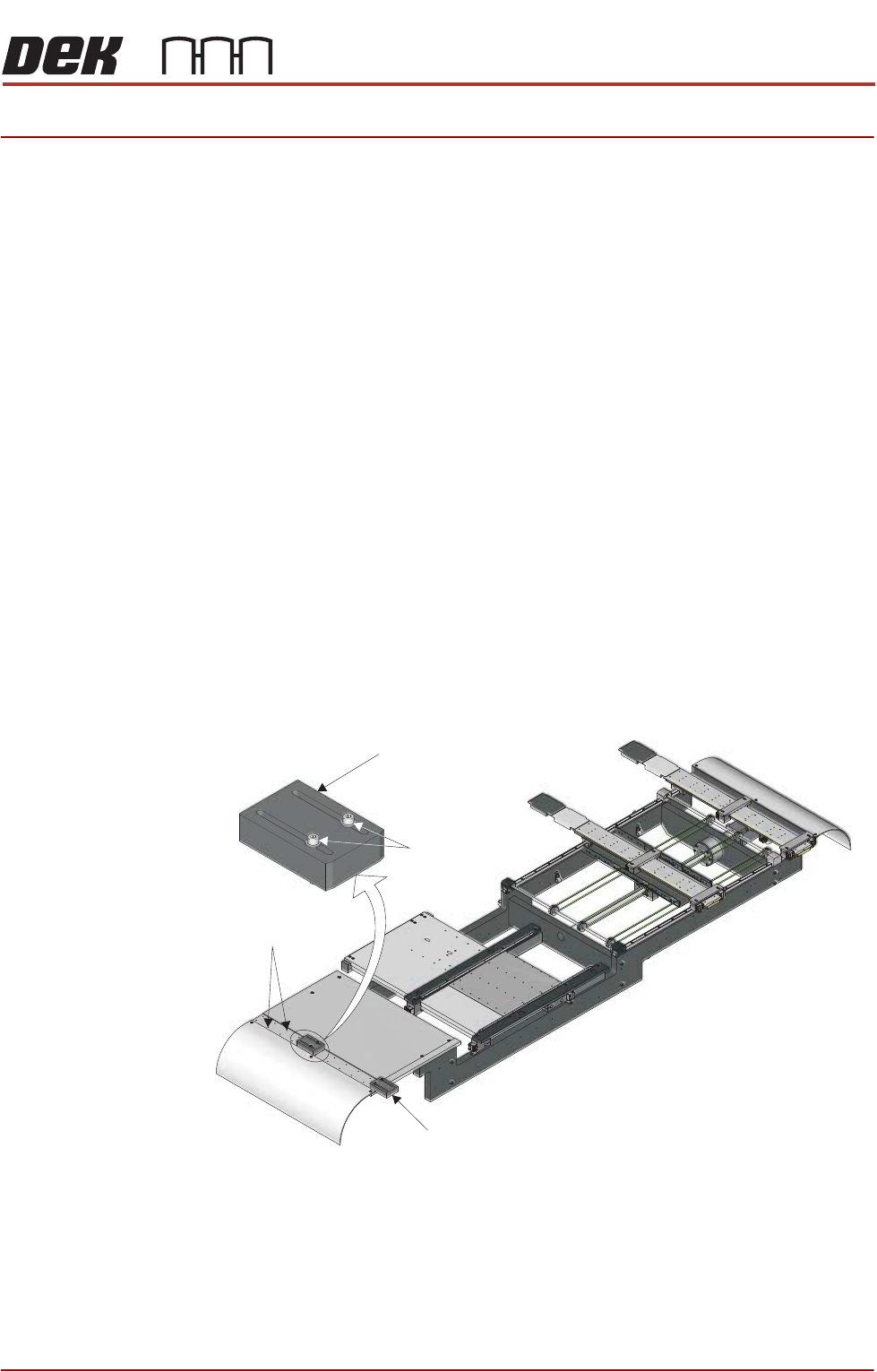
14. In the tooling area, using a 2.5mm Allen key, loosen the 2 rear rail securing
screws. These can be accessed through a hole in the top of the rear rail.
15. Move the rear rail towards the back of the machine.
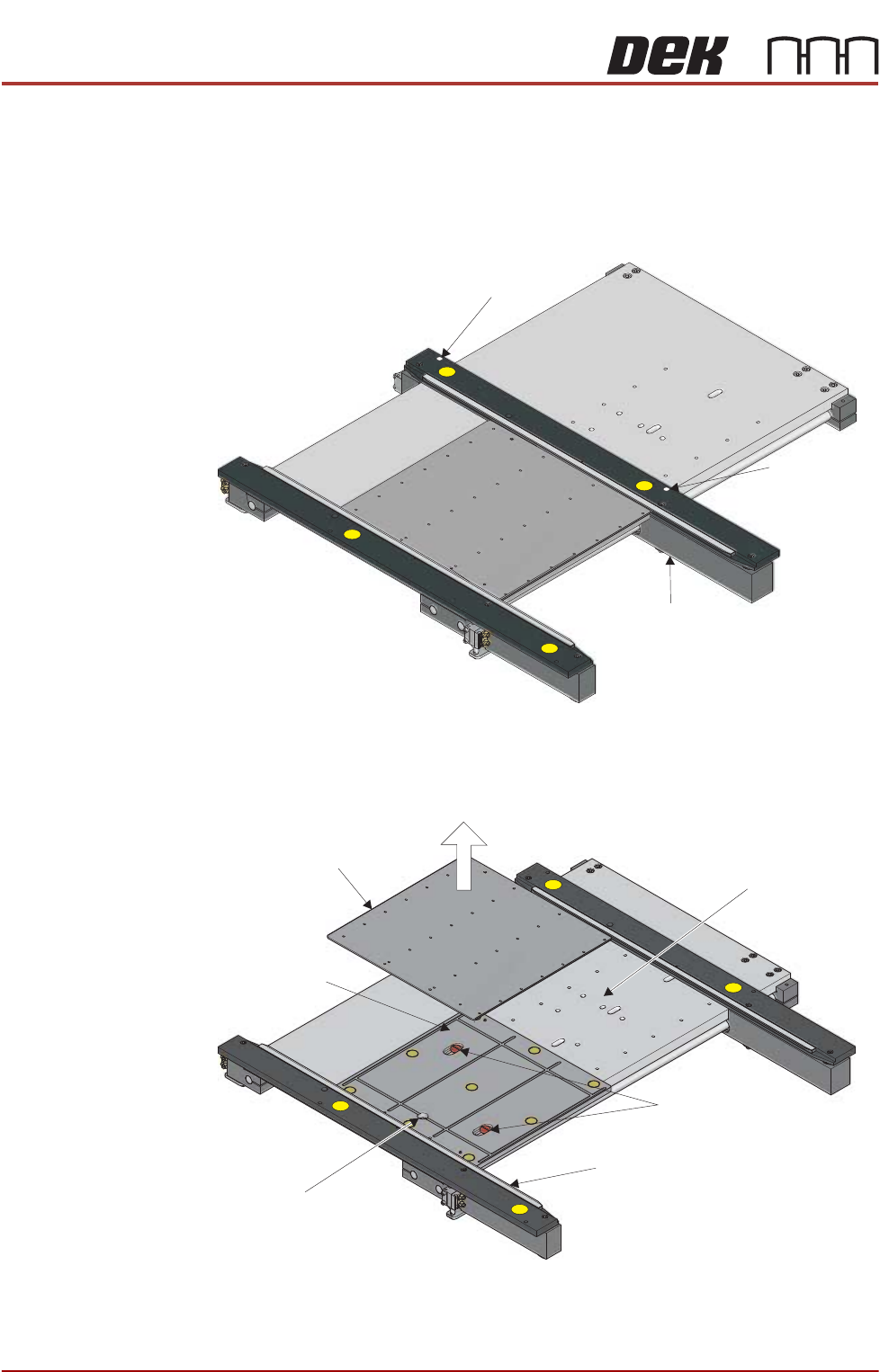
16. Lift out the tooling top plate, taking care not to damage the board clamp on
the front rail.
17. Using a flat bladed screwdriver, remove the two sandwich plate securing
screws.
Rail Securing Screw
Rail Securing
Screw
Rear Rail
Top Plate
Securing Screws
Board Clamp
Sandwich Plate
Vacuum Connection
Tooling Table