192866 Issue 4 - Reel to Reel Manual LoRes - 第27页
USER SETUP Chapter Issue 3, August 14 Reel to Reel Manual 2.3 18. Lif t out the sandwich plate, t aking care not to damage the board clamp on the front rail. 19. Place the replacement sandwich plate on the tooling t able…
USER
SETUP
2.2 Reel to Reel Manual Chapter Issue 3, August 14
product reel. Ensure the sample lays flat with no ripples or creases.
13. Tighten/refit the two adjustment screws.
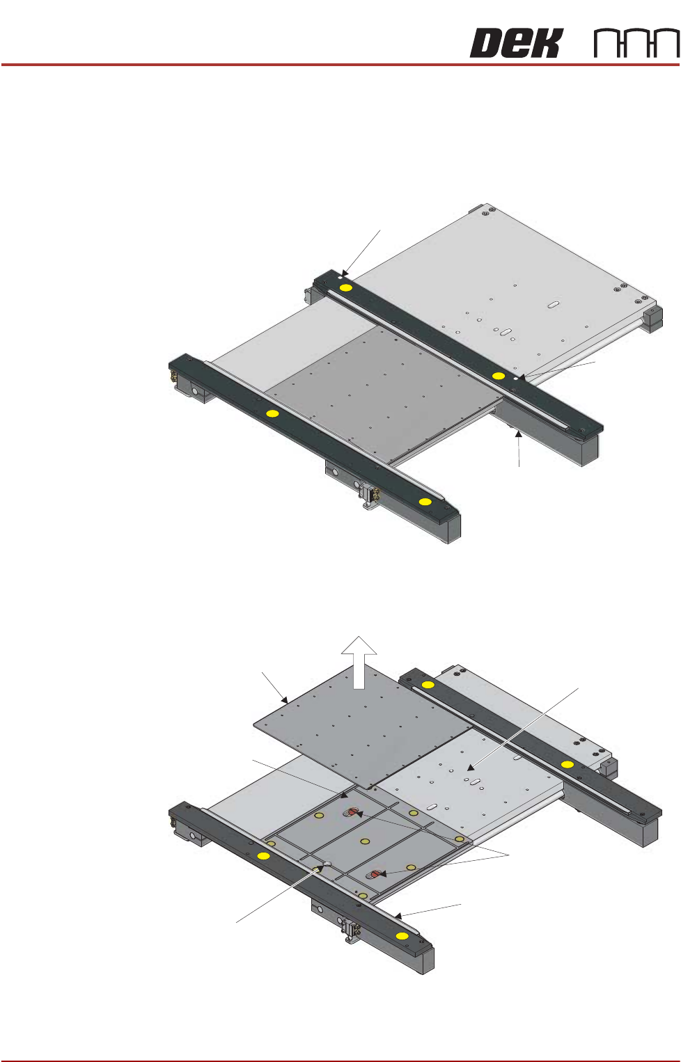
14. In the tooling area, using a 2.5mm Allen key, loosen the 2 rear rail securing
screws. These can be accessed through a hole in the top of the rear rail.
15. Move the rear rail towards the back of the machine.
16. Lift out the tooling top plate, taking care not to damage the board clamp on
the front rail.
17. Using a flat bladed screwdriver, remove the two sandwich plate securing
screws.
Rail Securing Screw
Rail Securing
Screw
Rear Rail
Top Plate
Securing Screws
Board Clamp
Sandwich Plate
Vacuum Connection
Tooling Table
USER
SETUP
Chapter Issue 3, August 14 Reel to Reel Manual 2.3
18. Lift out the sandwich plate, taking care not to damage the board clamp on
the front rail.
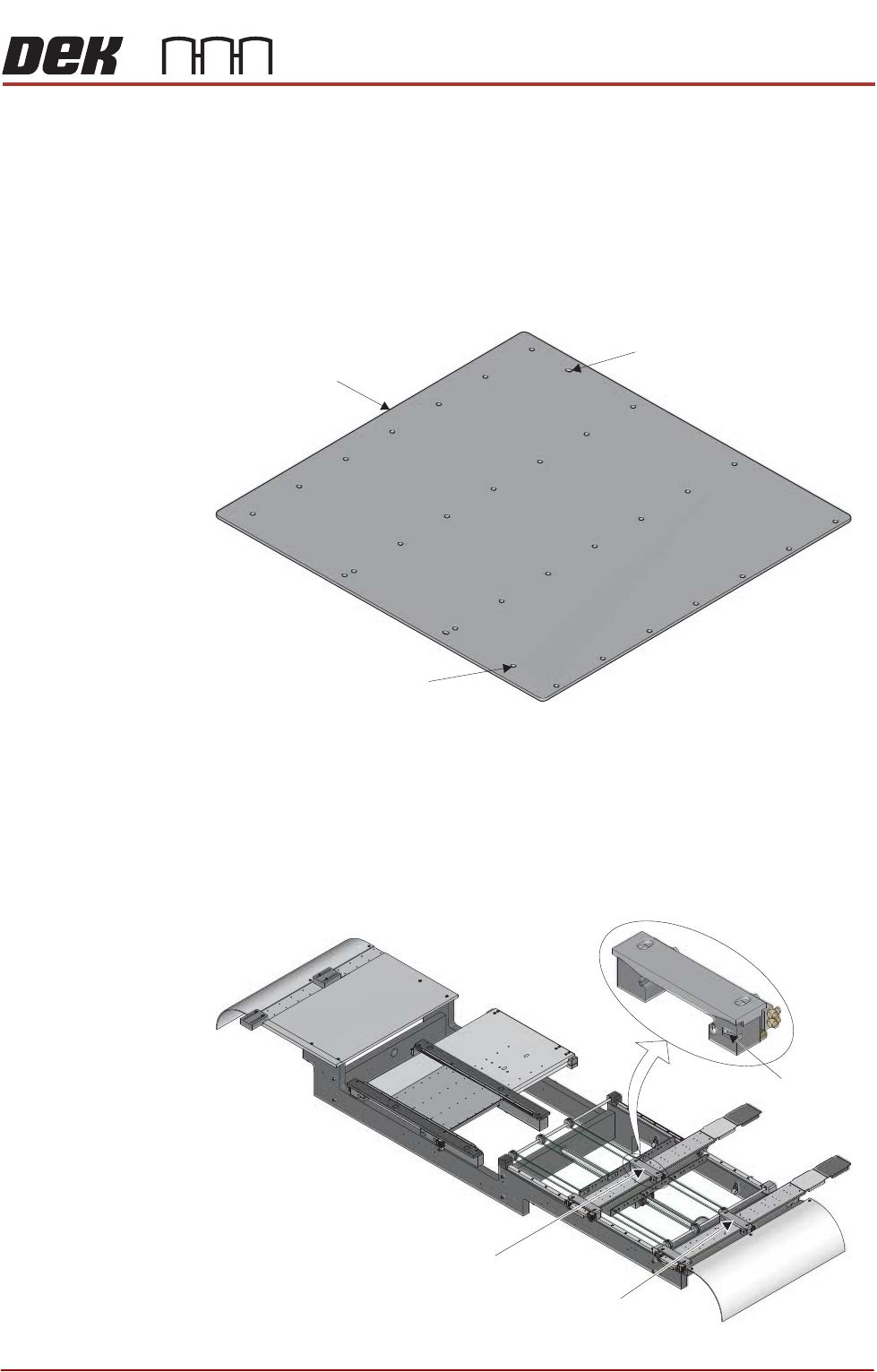
19. Place the replacement sandwich plate on the tooling table, ensure that the
plate is hard against the front rail and the dowel holes are aligned with the
plate below.
20. Refit the two securing screws.
21. There are two dowel holes on the replacement top plate. These align with
dowels on the sandwich plate. Locate the elongated dowel hole.
22. Place the replacement top plate on the sandwich plate, ensuring that the
elongated dowel hole is at the rear and the plate is hard against the front rail.
23. Move the rear rail towards the front of the machine ensuring that it is hard
against the top plate.
24. Tighten the two rear rail securing screws.
25. On the outroad conveyor, use a 2.5mm Allen key to loosen the securing
screw that secures the inner rear transport clamp.
Top Plate
Elongated Dowel Hole
Dowel Hole
Inner Rear Transport Clamp
Outer Rear Transport Clamp
Securing
Screw
USER
SETUP
2.4 Reel to Reel Manual Chapter Issue 3, August 14
26. Loosen the securing screw that secures the outer rear transport clamp.
27. Place a sample of the product reel against the inner and outer front transport
clamps and adjust the rear transport clamps to approximately 0.5mm of the
rear edge of the product reel. Ensure the sample lays flat with no ripples or
creases.
28. Tighten the adjustment screws on the inner and outer rear transport clamps.
29. The outroad transport clamps are adjustable as to how much of the clamp
overlaps the product reel. If the clamps do not need adjustment, go to Step
33.
NOTE
The more of the clamp on the product reel, the better. Printing to the edges
of the product reel may require the clamps to be adjusted away from the print
medium.
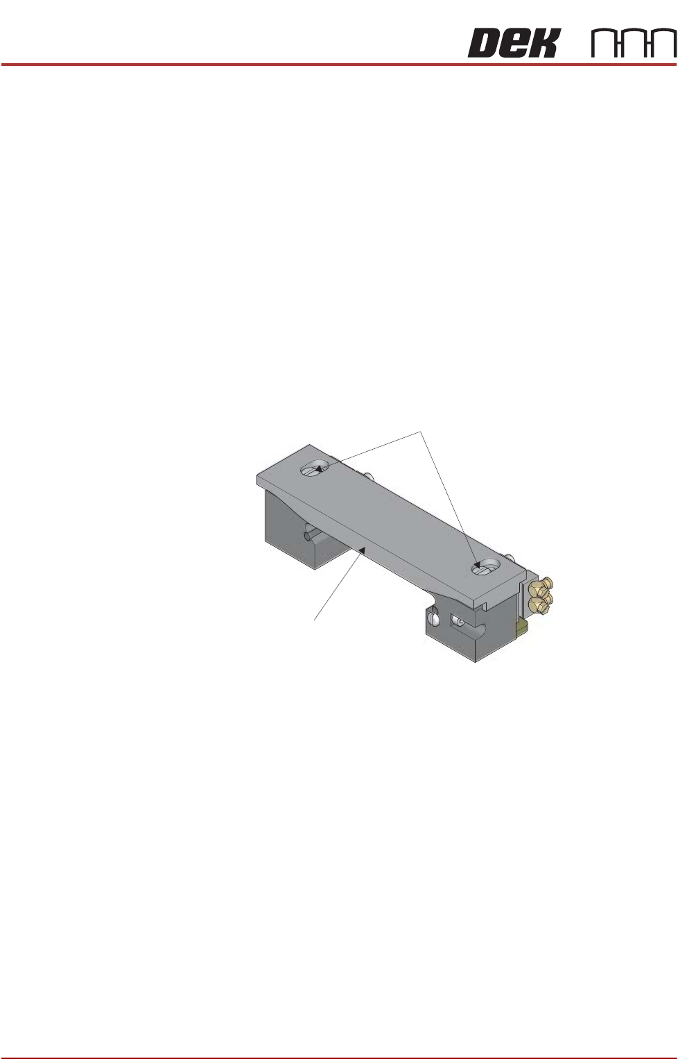
30. On the inner rear transport clamp, use a screwdriver to loosen the two
securing screws and adjust the top plate of the clamp to suit the product.
31. Tighten the two securing screws.
32. Repeat Steps 30 and 31 for the other three transport clamps.
33. Slide the vacuum covers over the inner and outer transport vacuum plate to
Clamp Top Plate
Securing
Screws