00194614-08 Trainingsdoku. SG X-Serie_X4i SW70x (AL2)_EN.pdf - 第101页
Communication and Control CAN Bus CAN Bus Communication with Axis Controller 101 Student Guide SIPLACE X-Serie and X4I SW70x (AL2) Overview axis controller
Communication and Control
CAN Bus Communication with Axis Controller CAN Bus
Student Guide SIPLACE X-Serie and X4I SW70x (AL2) 100
CAN Bus- Control led Func tions on the Twin Head
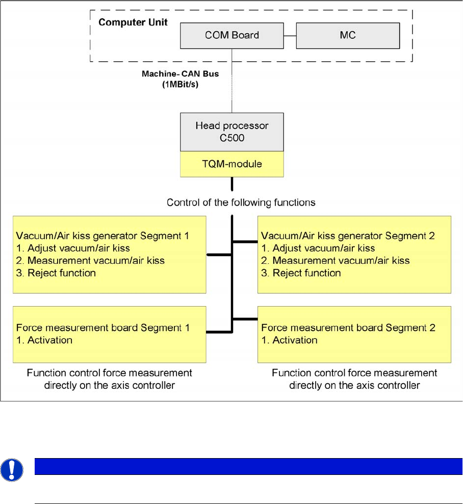
4.3.4.3 CAN Bus-Controlled Functions on the Twin Head
Function on the Can Bus Processor Twin head
The CAN bus processor board is no longer installed on each Twin segment, as in the case of the HF
machines. It can now be found at a central location on the head processor board C500.
CAN Bus Communication with Axis Controller
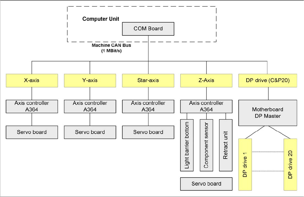
4.3.5 CAN Bus Communication with Axis Controller
The communication between the axis controller modules is now achieved using the CAN Bus. All the
information exchanged between these modules is transmitted via the CAN bus (e.g. axis parameter,
target position, end position signal, ...).
NOTICE
The status of the 16 bit processor board is indicated on the 7-segment display.
Normal status on the display is: "." flashes. (for description see Section C&P Head).
Communication and Control
CAN Bus CAN Bus Communication with Axis Controller
101 Student Guide SIPLACE X-Serie and X4I SW70x (AL2)
Overview axis controller
Communication and Control
Communication SIPLACE Vision CAN Bus
Student Guide SIPLACE X-Serie and X4I SW70x (AL2) 102
Communication SIPLAC E Vision
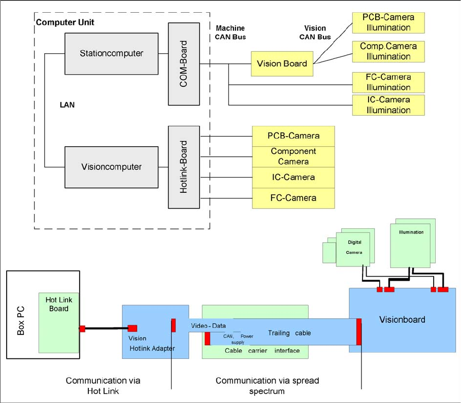
4.3.6 Communication SIPLACE Vision
Overview SIPLACE Vision
The communication between the computers is via LAN cables. The station computer sends the
commands for image acquisition to the Vision computer and receives the measurement result. The
station computer also sends the illumination values for the respective component shapes. The images
recorded are transferred digitally via the Vision board to the hotlink adapter, using the spread spectrum
and are then sent via the hotlink connection to the Vision computer, for evaluation. The result is sent to
the station computer.
Communication During Image Acquisition
4.3.6.1 Communication During Image Acquisition
The main communication between the Vision system and station computer is the transmission of
illumination values. These values, stored in the CS, are sent via CAN bus to the camera in question. As
soon as the camera should take the picture, the camera illumination is activated by a trigger. From this
moment on the row of LEDs which provides the different illumination levels shines according to the
illumination value. This illumination value can have 0 = dark up to 255 = bright. All illumination levels start
lighting at the same moment. The value 0-255 determines the length of the illumination time.
The maximum length of illumination is limited to 6 ms.