00194614-08 Trainingsdoku. SG X-Serie_X4i SW70x (AL2)_EN.pdf - 第118页
Communication and Control Axis Dynamic Basic s Axis Control Student Guide SIPLACE X-Serie and X4I SW70x (AL2) 118 During initial Positioning int o the target position, the actual equals target position signal triggers an…
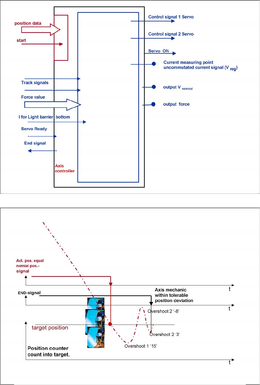
Communication and Control
Axis Control Axis Dynamic Basics
117 Student Guide SIPLACE X-Serie and X4I SW70x (AL2)
Digitally controlled axes for SIPLACE machine
Positioning with overshoot into target position
Communication and Control
Axis Dynamic Basics Axis Control
Student Guide SIPLACE X-Serie and X4I SW70x (AL2) 118
During initial Positioning into the target position, the actual equals target position signal triggers an
overshoot count in the axis test box (SAT) for the position deviation signal.
If the overshoot is greater than the permitted position deviation for this axis, the end position signal will
be delayed until the deviation has been regulated so that it is within the permitted range.
The 2nd overshoot sets the end signal
Positioning with asymptotic approach after the initial, excessive overshoot
NOTICE
The position deviation signal shows the positioning quality of an axis movement in position.
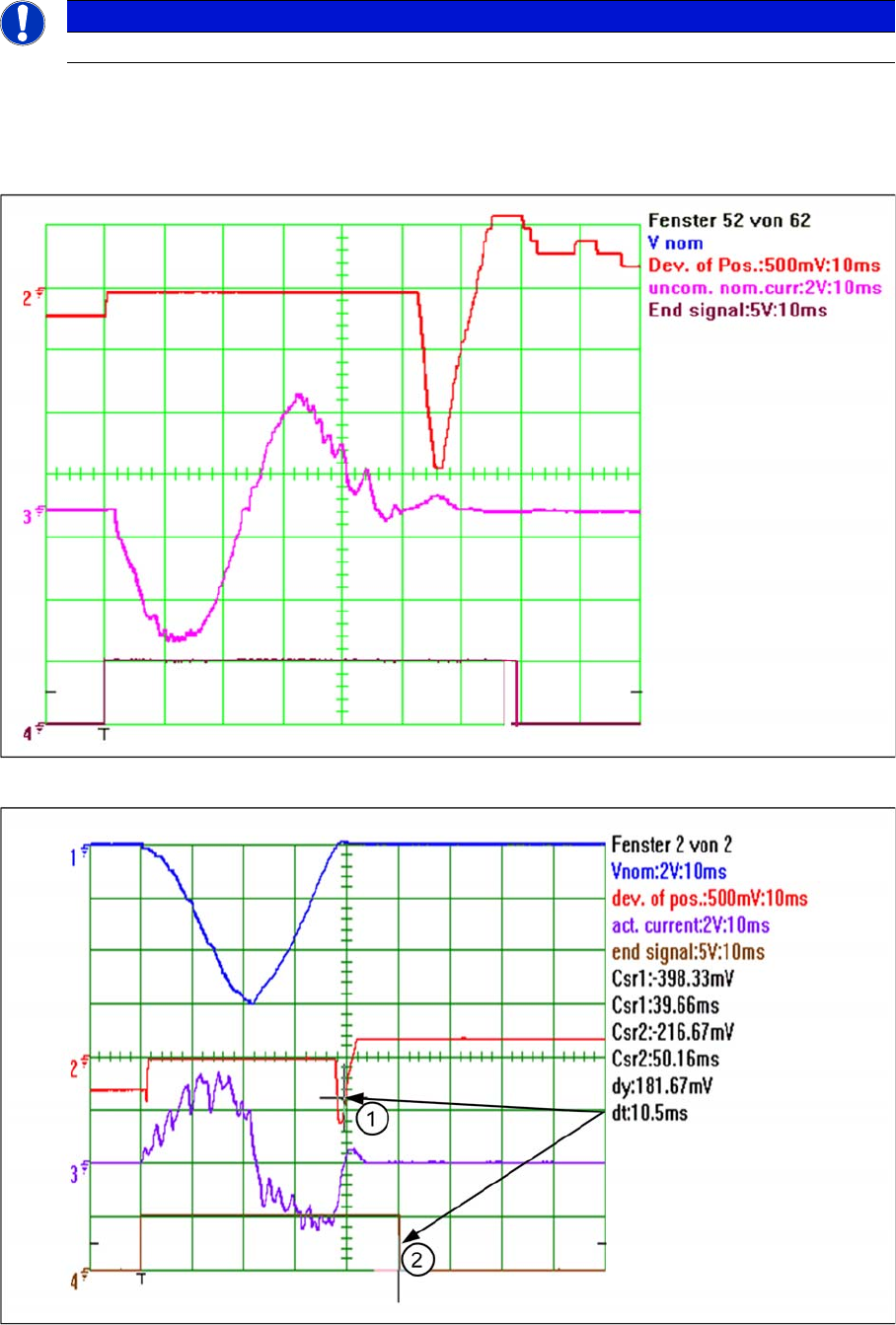
Communication and Control
Axis Control Axis Dynamic Basics
119 Student Guide SIPLACE X-Serie and X4I SW70x (AL2)
The positioning shown above demonstrates an excessive overshoot. However, no other overshoot, for
which an end signal could be issued, will occur during this positioning run. The axis controller has a
’backup strategy’ - When the permitted position deviation range is reached, a 10ms timer is started. 10
ms after entering the permissible range (here 5 digits (1)) the timer triggers the end position signal (2).
The permitted range must not be left during this period.
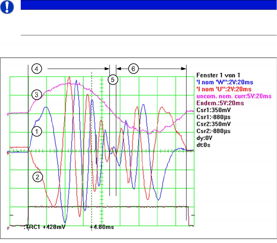
The system generates an uncommutated current target signal from all motor current target signals for
assessment of the axis dynamics by a service technician. This signal gives information about the
mechanical friction in the axis system. This can be measured on the adapter board of the axis test box
or at the Vreg output of the SIPLACE axis tester (SAT).
The uncommutated target current signal is an envelope signal for the 2 visible motor current target
signals from the axis controller. The 3rd motor current target signal (not visible) is calculated on the servo
amplifier board.
The known V nominal (Vnom) speed signal and the force signal have been replaced by the motor current
nominal signals for DC or AC drives.
The uncommutated motor current nominal signal (3) and the motor current signals (1) (2) of an AC motor
The acceleration section can be recognized in the motor current nominal signal of the AC motor (4) due
to the high amplitudes needed to supply the axis mechanics with sufficient force. The frequency of this
signal section is low, due to the low speed. The amplitude becomes lower and lower because the
necessary motor force is reduced with increasing speed.
The frequency increases as the speed of the motor rises, up to the maximum frequency for maximum
axis speed (5).
NOTICE
These motor current signals can be measured at the V nominal and the Force output of the axis
tester. The same signals are measurable at the 2 uppermost test pins on the servo amplifier
board, as Inom. U’ and Inom. W signals.