00194614-08 Trainingsdoku. SG X-Serie_X4i SW70x (AL2)_EN.pdf - 第123页
Communication and Control One Wire Bus One Wire Bus - Structure 123 Student Guide SIPLACE X-Serie and X4I SW70x (AL2) The A364 a xis ca rd is equippe d with two processors (module 1 a n d module 2) i.e. o ne processor co…
Communication and Control
Axis controller Axis Control
Student Guide SIPLACE X-Serie and X4I SW70x (AL2) 122
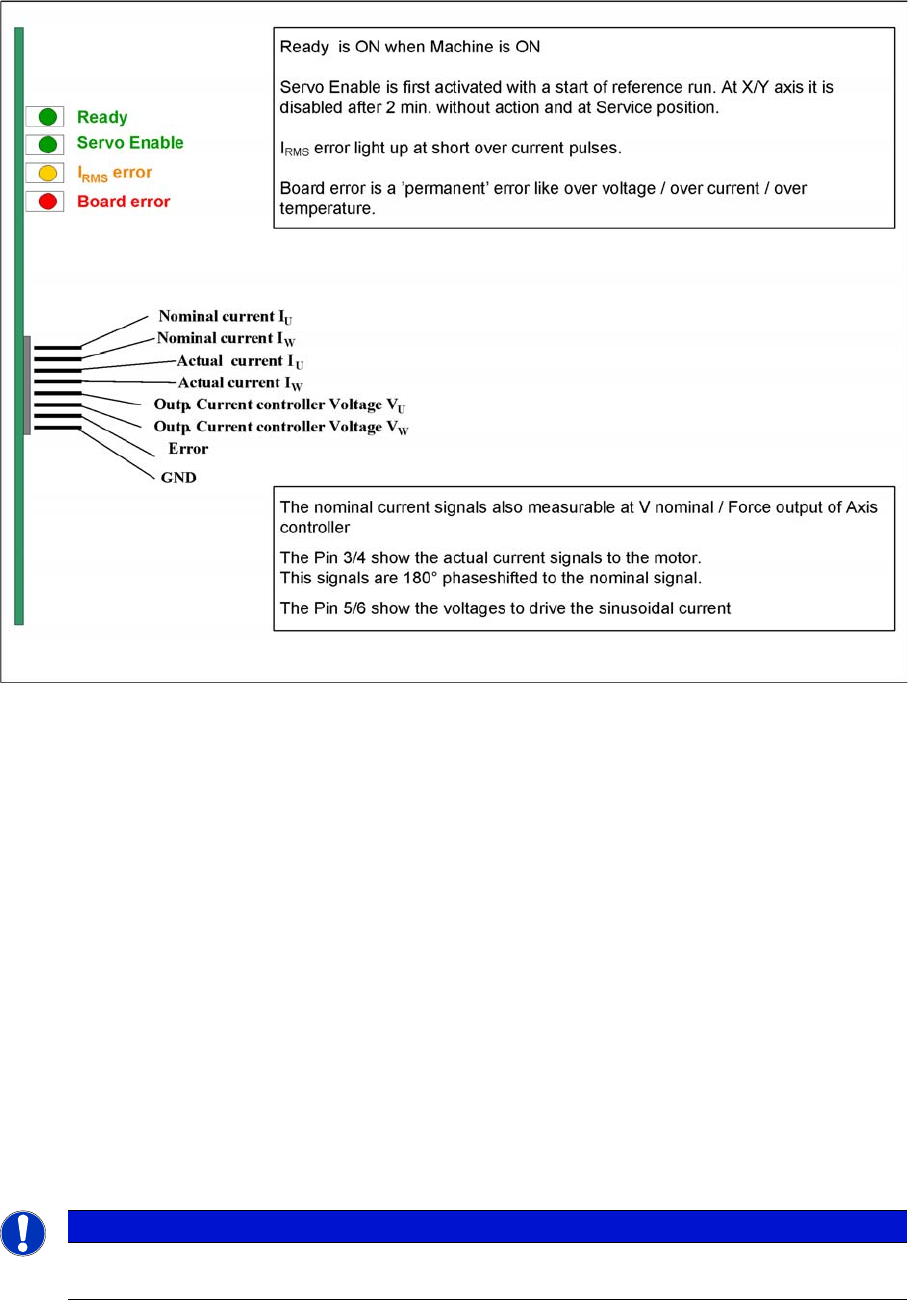
Servo Amplifi er TBS .. and SDS ...
4.4.3.2 Servo Amplifier TBS .. and SDS ...
Servo amplifier
Servo amplifiers of type TBS are used for the X/Y and star axes, while SDS servo amplifiers are used
for the Z and DP axes.
These SDS and TBS servo amplifiers can be reset with the servo disable/enable switch on the axis
controller board.
All servos are individually set for the maximum motor current of the drive unit connected. This mean that
the servo amplifiers need to be used on an axis-specific basis.
Measurement Pin MP7:
In the event of an error on the servo amplifier, you can measure various voltages at the analog output
pin MP7, to determine the error.
▪ Overvoltage -1 V
▪ Overcurrent -2 V
▪ Overtemperature -3 V
▪ Nominal current exceeded -4 V
SIPLACE Diagnos is Adapter A364 [03051220-0 1]
4.4.3.3 SIPLACE Diagnosis Adapter A364 [03051220-01]
Application:
The adapter card is used to check the A364 axis card dynamics.
NOTICE
This adapter is designed for all machines with A364 and as an adapter for the CAN test box
with force measuring tool.
Communication and Control
One Wire Bus One Wire Bus - Structure
123 Student Guide SIPLACE X-Serie and X4I SW70x (AL2)
The A364 axis card is equipped with two processors (module 1 and module 2) i.e. one processor controls
two axes.
One Wir e Bus
4.5 One Wire Bus
The one wire bus in the SIPLACE X4I is used for requests between the temperature sensors and the
head plates and for reading out the gantry type. The nozzle changer control and sensor requests for the
reject bin are established via a so-called CAN node (see Chapter Component Handling).
Tasks:
1. 2 temperature sensors per gantry (fixed to the head plate).
2. Storage of gantry identification on an EEPROM.
A differentiation is made between plate gantry CFK-02, Design To Cost (DTC) gantry CFK-04 and
CFK 06 gantry. This means that the machine database loaded for the dynamic parameters of the
main axis differs according to the gantry type concerned.
One Wire B us - Structure
4.5.1 One Wire Bus - Structure
As the name indicates, the data are transferred (serial transfer) via a single wire, to the relevant
subsystem. The one wire bus system is used for processes where time is not a critical factor and can be
realized as a single master bus with „any number“ of slaves (stations).
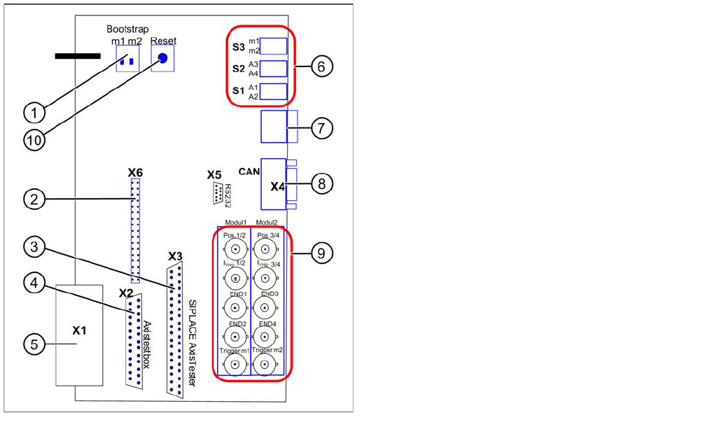
Adapter card for A364
Legend
Module 1: Axis 1/2
Module 2: Axis 3/4
1. Bootstrap mode: m1 = module1 / m2 = module2
2. Diagnosis – connector X6
3. Connection X3 SIPLACE AxisTester
4. Connection X2 Axis test box
5. Connection X1 to A364
6. Switches:
7. Diagnosis – 7 segment display
8. CAN bus connector (Sub-D)
9. BNC sockets:
10. Reset both processors
Communication and Control
One Wire Bus - Structure One Wire Bus
Student Guide SIPLACE X-Serie and X4I SW70x (AL2) 124
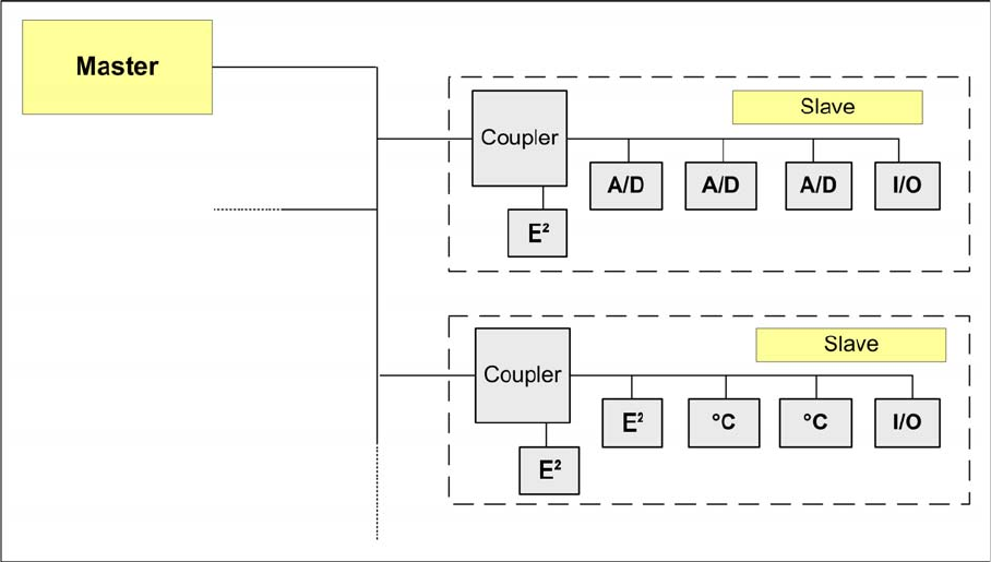
Basic Structure
4.5.1.1 Basic Structure
One wire bus principle
The one wire bus system consists in principle of a master with EEPROM (control unit), which controls
the various submodules such as A/D converters, EEPROM, temperature and I/O modules. Each
communication branch is equipped with an upstream coupler, which opens the branch for data transfer..