00194614-08 Trainingsdoku. SG X-Serie_X4i SW70x (AL2)_EN.pdf - 第131页
Communication and Control One Wire Bus Function Control and Troubleshooting for Service Work 131 Student Guide SIPLACE X-Serie and X4I SW70x (AL2) Assignment X Series (up to S W 60x) PA1 Assignment X Series (up to SW 60x…

Communication and Control
Function Control and Troubleshooting for Service Work One Wire Bus
Student Guide SIPLACE X-Serie and X4I SW70x (AL2) 130
Allocation o f Subsystems to the Hardware Components
Allocation of Subsystems to the Hardware Components
Assignme nt HF/HF3 PA1
Assignment HF/HF3 PA1
SIPLACE HF/HF3 - PA1
Subsystem Hardware components Comments
Temperature, 1, coupler, 00 PCB: 1 wire trailing
interface
Trailing interface gantry 1
Temperature, 4, coupler, 00 PCB: 1 wire trailing
interface
Trailing interface gantry 4
NC, 4, coupler, 00 1 wire hub for NC Hub for NC at location 4 for NC row 1/2
NC, 1, coupler, 00 1 wire hub for NC Hub for NC at location 1 for NC row 1/2
Mainpath, 0, IO_2C, 01
Mainpath, 0, E2_512B, 01
I/O submodule I/O module, the-1-Wire-CAT5 board
interface will be integrated later into the
I/O module
Temperature, 1, E2_512B, 81
Temperature, 1, E2_32B, 01
Temperature, 1, E2_512B, 61
Temperature, 1, temperature, 10
Temperature, 1, temperature, 11
Temperature, 1, IO_2C,01
Temperature sensors
Gantry 1
The two temperature sensors form a unit
and can only be replaced as a set. The
gantry recognition part can not be
replaced.
Temperature, 4, E2_512B, 81
Temperature, 4, E2_32B, 01
Temperature, 4, E2_512B, 61
Temperature, 4, temperature, 10
Temperature, 4, temperature, 11
Temperature, 4, IO_2C,01
Temperature sensors
Gantry 4
The two temperature sensors form a unit
and can only be replaced as a set. The
gantry recognition part can not be
replaced.
NC, 4, E2 32B, 81
NC, 4, AD, 03
NC, 4, AD, 15
NC, 4, AD, 16
1 wire hub NC on location
4
Shows, that the 1 wire hub is connected.
NC, 4, E2_32, 01
NC, 4, AD, 01
NC, 4, IO_8C, 01
Control board in NC
Gantry 4, only for
C&P20A NC
Control board of NC row 1
(only for C&P20A NC).
NC, 4, E2_32, 02
NC, 4, AD, 02
NC, 4, IO_8C, 02
Control board in NC
Gantry 4, only for
C&P20A NC
Control board of NC row 2
(only for C&P20A NC).
NC, 1, E2_32B, 81
NC, 1, AD, 03
NC, 1, AD, 15
NC, 1, AD, 16
1 wire hub NC on location
1
Shows that the 1 wire hub is connected.
NC, 1, E2_32B, 01
NC, 1, AD, 01
NC, 1, IO_8C, 01
Control board in NC
Gantry 1, only for
C&P20A NC
Control board of NC row 1
(only for C&P20A NC).
NC, 1, E2_32B, 02
NC, 1, AD, 02
NC, 1, IO_8C, 02
Control board in NC
Gantry 1, only for
C&P20A NC
Control board of NC row 2
(only for C&P20A NC).

Communication and Control
One Wire Bus Function Control and Troubleshooting for Service Work
131 Student Guide SIPLACE X-Serie and X4I SW70x (AL2)
Assignment X Series (up to S W 60x) PA1
Assignment X Series (up to SW 60x) PA1
SIPLACE X-series - PA1
Assignment X4I and X Series (from SW 70x) PA1
Assignment X4I and X Series (from SW 70x) PA1
SIPLACE X4I - PA1
Subsystem Hardware components Comments
NC, 1, coupler, 00 1-Wire CAT5 interface
on the I/O module
Temperature, 20, coupler, 00 1-Wire CAT5 interface
on the I/O module
NC, 4, coupler, 00 1-Wire CAT5 interface
on the I/O module
Mainpath, 0, IO_2C, 01
Mainpath, 0, E2_512B, 01
1-Wire CAT5 interface
on the I/O module
1-Wire-CAT5 board interface will be
integrated later into the I/O module
Temperature, 20, E2_32B, 01
temperature, 20, E2_512B, 61
Temperature, 20, temperature, 10
Temperature, 20, temperature, 11
Temperature, 1, IO_2C,01
Temperature sensors
Gantry 1
The two temperature sensors form a unit
and can only be replaced as a set. The
gantry recognition part can not be
replaced.
Temperature, 20, E2_32B, 81
Temperature, 20, E2_512B, e1
Temperature, 20, temperature, 90
Temperature, 20, temperature, 91
Temperature, 20, IO_2C,81
Temperature sensors
gantry 4
The two temperature sensors form a unit
and can only be replaced as a set. The
gantry recognition part can not be
replaced.
NC, 4, AD, 03
NC, 4, AD, 01
NC, 4, AD, 81
1 wire hub NC on
location 4
Shows, that the 1 wire hub is connected.
NC, 4, E2_32B, 01
NC, 4, IO_8C, 01
NC, 4, AD, 01
Control board in NC
Gantry 4, only for
C&P20A NC
Control board of NC row 1
(only for C&P20A NC).
NC, 4, E2_32B, 81
NC, 4, IO_8C, 81
NC, 4, AD, 97
Control board in NC
Gantry 4, only for
C&P20A NC
Control board of NC row 2
(only for C&P20A NC).
NC, 1, AD, 01
NC, 1, AD, 03
NC, 1, AD, 81
1 wire hub NC on
location 1
Shows, that the 1 wire hub is connected.
NC, 1, E2_32B, 01
NC, 1, IO_8C, 01
NC,1 AD, 15
Control board in NC
Gantry 1, only for
C&P20A NC
Control board of NC row 1
(only for C&P20A NC).
NC, 1, E2_32B, 81
NC, 1, IO_8C, 81
NC, 1, AD, 97
Control board in NC
Gantry 1, only for
C&P20A NC
Control board of NC row 2
(only for C&P20A NC).
Subsystem Hardware components Comments
NC, 1, coupler, 00 1-Wire CAT5 interface
on the I/O module
Not needed, as the NC operates with
CAN nodes.
Temperature, 20, coupler, 00 1-Wire CAT5 interface
on the I/O module
NC, 4, coupler, 00 1-Wire CAT5 interface
on the I/O module
Not needed, as the NC operates with
CAN nodes.
Communication and Control
Function Control and Troubleshooting for Service Work One Wire Bus
Student Guide SIPLACE X-Serie and X4I SW70x (AL2) 132
Function Control with Caccia
4.5.2.2 Function Control with Caccia
Example - nozzle changer (NC)
In addition to the station software, there are also two other means for checking the function of the NC.
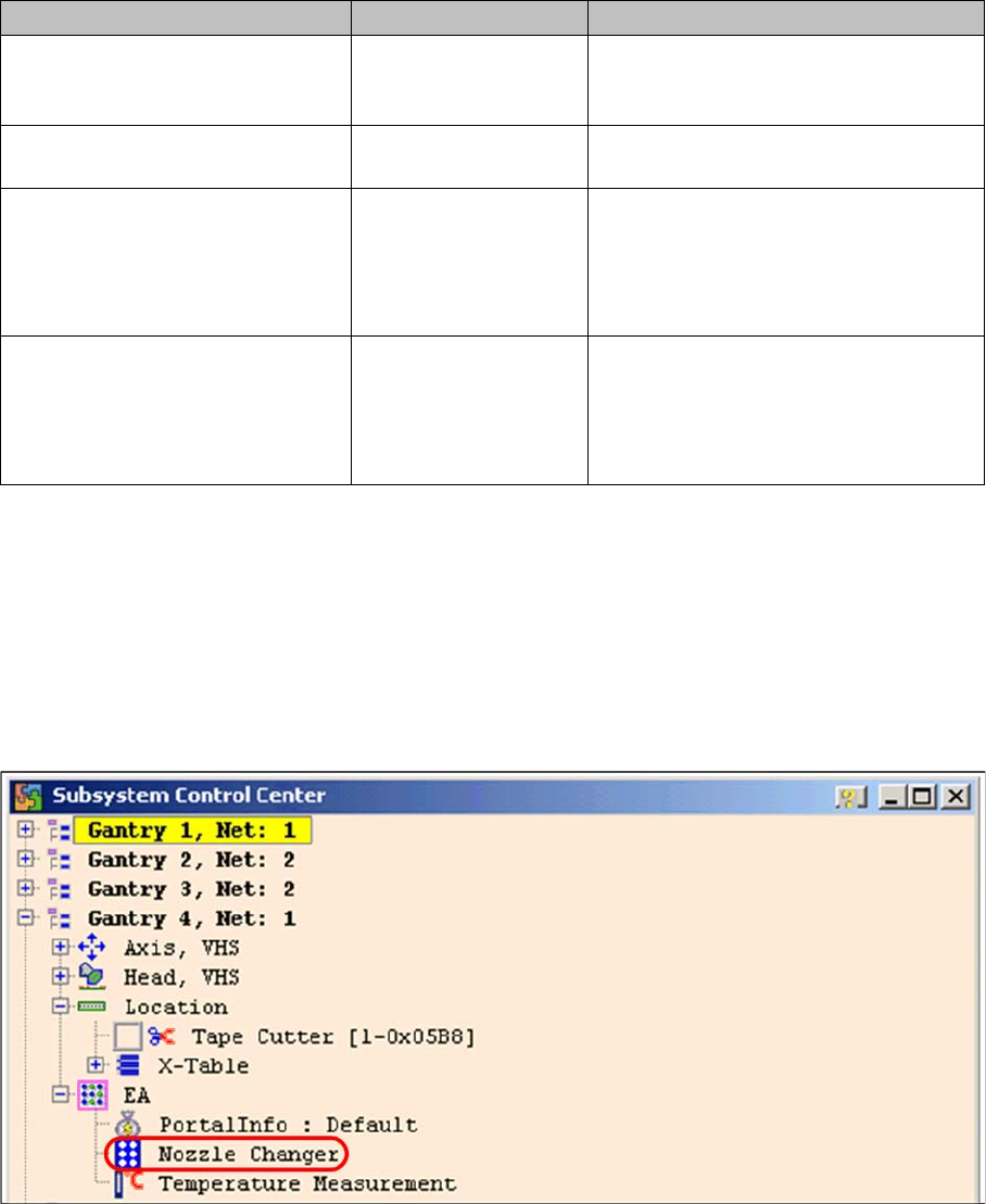
NC menu
NC menu
► Open the IO folder for the relevant location in the Subsystem control center.
► Double-click on Nozzle Changer
Subsystem control center (nozzle changer)
► the following menu will appear:
Mainpath, 0, IO_2C, 01
Mainpath, 0, E2_512B, 01
1-Wire CAT5 interface
on the I/O module
1-Wire-CAT5 board interface will be
integrated later into the I/O module
version 03
Temperature, 1, IO_2C,01
Temperature, 20, IO_2C,81
1-Wire CAT5 interface
on the I/O module
Temperature, 20, E2_32B, 01
temperature, 20, E2_512B, 61
Temperature, 20, temperature, 10
Temperature, 20, temperature, 11
Temperature, 1, IO_2C,01
Temperature sensors
Gantry 4
The two temperature sensors form a unit
and can only be replaced as a set. The
gantry recognition part can not be
replaced.
Temperature, 20, E2_32B, 81
Temperature, 20, E2_512B, e1
Temperature, 20, temperature, 90
Temperature, 20, temperature, 91
Temperature, 20, IO_2C,81
Temperature sensors
Gantry 1
The two temperature sensors form a unit
and can only be replaced as a set. The
gantry recognition part can not be
replaced.
Subsystem Hardware components Comments