00194614-08 Trainingsdoku. SG X-Serie_X4i SW70x (AL2)_EN.pdf - 第136页
Communication and Control One Wire Bus SIPLACE X Machine One Wire Bus Student Guide SIPLACE X-Serie and X4I SW70x (AL2) 136 One Wir e Communication 4.5.3.1 One Wire Communication Communication with the one wire inte rfac…

Communication and Control
One Wire Bus One Wire Bus SIPLACE X Machine
135 Student Guide SIPLACE X-Serie and X4I SW70x (AL2)
▪Select Send
▪ Acknowledge:
6a 00 00 --> reject bin not present
6a 00 01 --> reject bin present
CAN Bus Commands For Checking the Temperature Sensors
CAN Bus Commands For Checking the Temperature Sensors
▪Command: 6e 11 01 01 28 10
6e 11 --> command
01 --> not def.
01 --> Gantry 1
28 --> Subsystem temperature
10 --> Temperature sensor at top, on the head plate (16)
▪Select Send
▪ Acknowledge: 6e 00 1c 4b -->
6e 00 --> command
1c --> Temperature value 1c hex --> 28°C
▪Command: 6e 11 01 01 28 11
6e 11 --> command
01 --> not def.
01 --> Gantry 1
28 --> Subsystem temperature
11 --> Temperature sensor at bottom, on the head plate (17)
▪Select Send
▪ Acknowledge: 6e 00 1d 4b -->
6e 00 --> command
1d --> Temperature value 1d hex --> 29°C
CAN Bus Com mands for Ini tializing the One Wire Bus
CAN Bus Commands for Initializing the One Wire Bus
▪Command: 3d 01
3d 01 --> initialization command
▪Select Send
▪ Acknowledge: 3d 00 01 Initialization successful.
One Wire B us SIPLACE X Ma chine
4.5.3 One Wire Bus SIPLACE X Machine
The structure of the SIPLACE X and X4I machines has been changed. This results in a different
hardware structure of the bus system and the subsystems to the hardware components.
During the initialization procedure, the subsystems independently log themselves on to the one wire bus
via the public byte. The public byte is sent via the CAN ID +3hex of the relevant subsystem. If the state
of a subsystem changes, the subsystem reports automatically and without a request from the
application.
See also
4.5.2.1.1 Allocation of Subsystems to the Hardware Components [ ➙ 130]
NOTICE
The reject bins request is sent via the message loop. This means that you must first close the
whole security loop (table, cover,...) before the software can check and display the state of the
message loop (e.g.missing reject bins).
Communication and Control
One Wire Bus SIPLACE X Machine One Wire Bus
Student Guide SIPLACE X-Serie and X4I SW70x (AL2) 136
One Wir e Communication
4.5.3.1 One Wire Communication
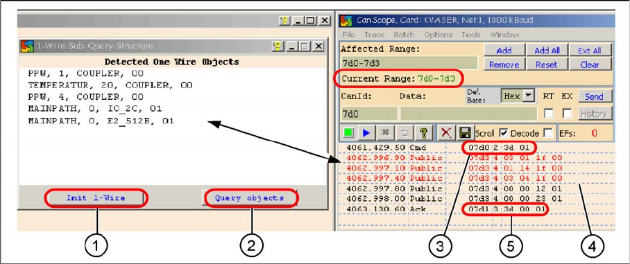
Communication with the one wire interface RS232 on the I/O module
Legend
1. Init 1 Wire sends the command via the CAN ID 7d0 (PA1)
2. Query objects shows the decoded public bytes.
3. Net window: 07d0 3d 01 Command initialization for the one wire bus.
4. 5 public bytes from subsystem 1-Wire CAT5 interface on the I/O module
1. 03 01 1f 00 --> 03 Subsystem NC / 01 Gantry / 1f Coupler
2. 01 14 1f 00 --> 01 Subsystem temperature gantry 1/4 / 14 1k EEPROM / 1f Coupler
3. 03 04 1f 00 --> 03 Subsystem NC / 04 Gantry / 1f Coupler
4. 00 00 12 01 --> 12 I/O component and EEPROM
5. 00 00 23 01 --> 23 4k EEPROM
5. Acknowledge (Ack) command CAN ID +1hex --> 3d 00 01
Communication and Control
Board IDs What are Board IDs?
137 Student Guide SIPLACE X-Serie and X4I SW70x (AL2)
Overview of O ne Wire B us Initializat ion
4.5.3.2 Overview of One Wire Bus Initialization
Board IDs
4.6 Board IDs
What are Board IDs?
4.6.1 What are Board IDs?
The board ID is an identification number, which is saved in an EEPROM. These ID‘s identify the boards
(head interface, head adapter,...) in the machine via software. Each board which communicates with a
TQM module, has an EEPROM with a unique ID. These board IDs are read and checked by the BIOS
in the TQM module.
Why Have We Introduced B oard ID s?
4.6.1.1 Why Have We Introduced Board IDs?
The introduction of board IDs has the benefit that only one BIOS version can be used for all TQM
modules in the machine.
Benefits:
▪ Simple to use for developers, setup engineers and service engineers
▪ Updates by developers only required for one BIOS version
▪ Storage, one SAP number for TQM modules (16 bit processor)
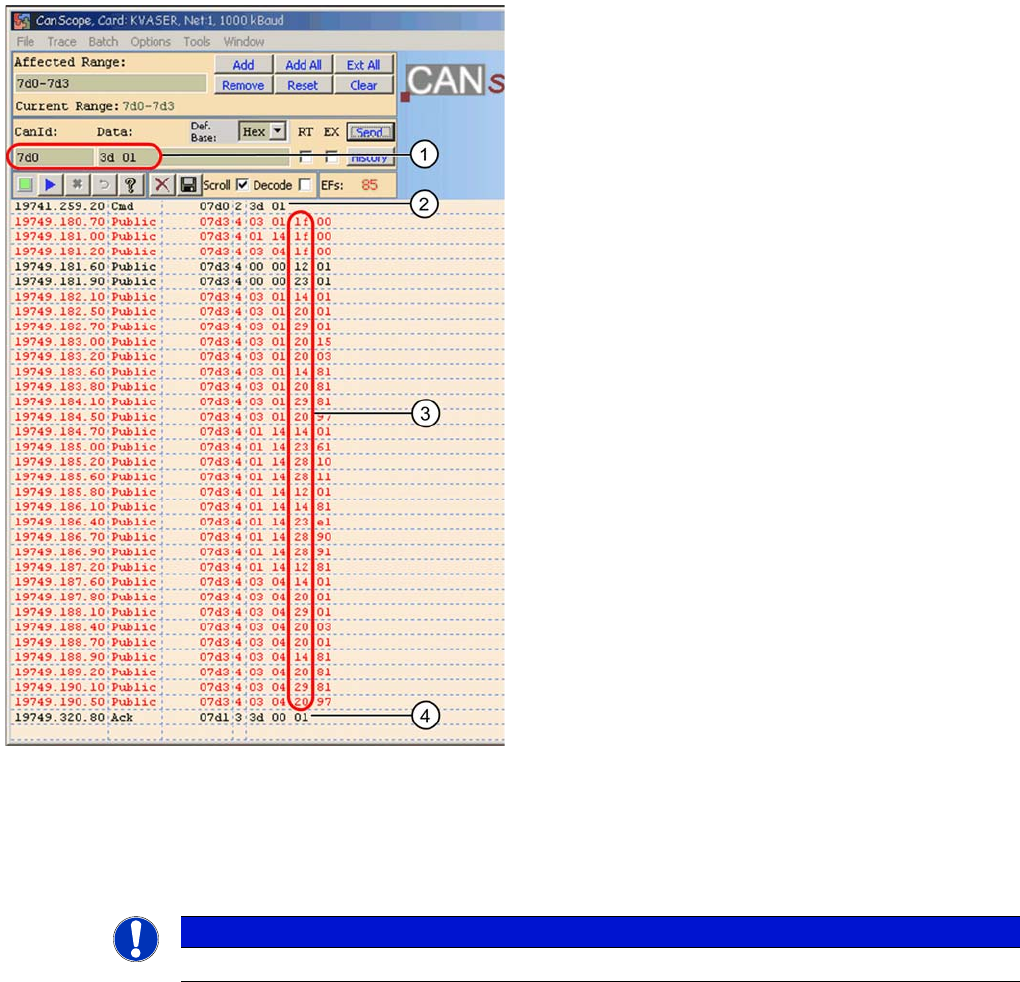
Legend
1. CAN BUS command for initialization
2. CAN BUS command sent.
3. Subsystems report, public bytes
1f --> Coupler
12 --> IO component with EEPROM
14 --> 1k EEPROM
20 --> 4 channel A/D
23 --> 4k EEPROM
28 --> Temperature
29 --> 8-fold IO component
4. Ack initialization successful.
NOTICE
Board IDs have nothing to do with the recognition of boards by the PCB barcode option.