00194614-08 Trainingsdoku. SG X-Serie_X4i SW70x (AL2)_EN.pdf - 第139页
Communication and Control Board IDs What are Board IDs? 139 Student Guide SIPLACE X-Serie and X4I SW70x (AL2) SIPLACE X series: ▪ Head interface (gantry 1 - 4) ▪ Head adapter (C&P20, C&P6/1 2, Twin head) ▪ Interm…
Communication and Control
What are Board IDs? Board IDs
Student Guide SIPLACE X-Serie and X4I SW70x (AL2) 138
The introduction of one BIOS version on the TQM Modules, for the different subsystems, was necessary
for the option Head Modularity.
Function
4.6.1.2 Function
During the booting phase, the TQM module BIOS sends a request for the board ID and thereby
recognizes which boards are connected for the placement head used or on which board the TQM
module is used. If all IDs are recognized and if they are all plausible, the application software will be
loaded. From SW 601.02, the station software issues an error message, if it does not recognize any of
the IDs or if it there is no plausible ID. This error message is currently only shown on the 7-segment
display of the TQM module.
Error Description for Missing IDs:
4.6.1.3 Error Description for Missing IDs:
When the BIOS and Application software are downloaded and the BIOS is unable to recognize one ID,
it will give an error on the seven segment display for a short time. The error message appears three
times, after that the application software starts up. The machine still starts up and can produce. If the
BIOS is unable to recognize more than one ID, the TQM module in the BIOS stops with an error code
on the 7 segment display. The machine will not boot and an error message will appear at the station and
on the 7-segment display of the TQM module (see error list).
The following ID‘s are saved in the PCB‘s EEPROM:
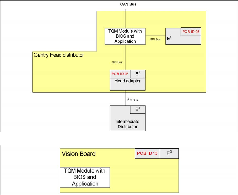
SIPLACE D series:
▪ Gantry Head Distributor
▪ Vision board
Overview of board IDs, checked by the TQM module (SIPLACE D)
Board IDs for Vision boards (SIPLACE D)
Communication and Control
Board IDs What are Board IDs?
139 Student Guide SIPLACE X-Serie and X4I SW70x (AL2)
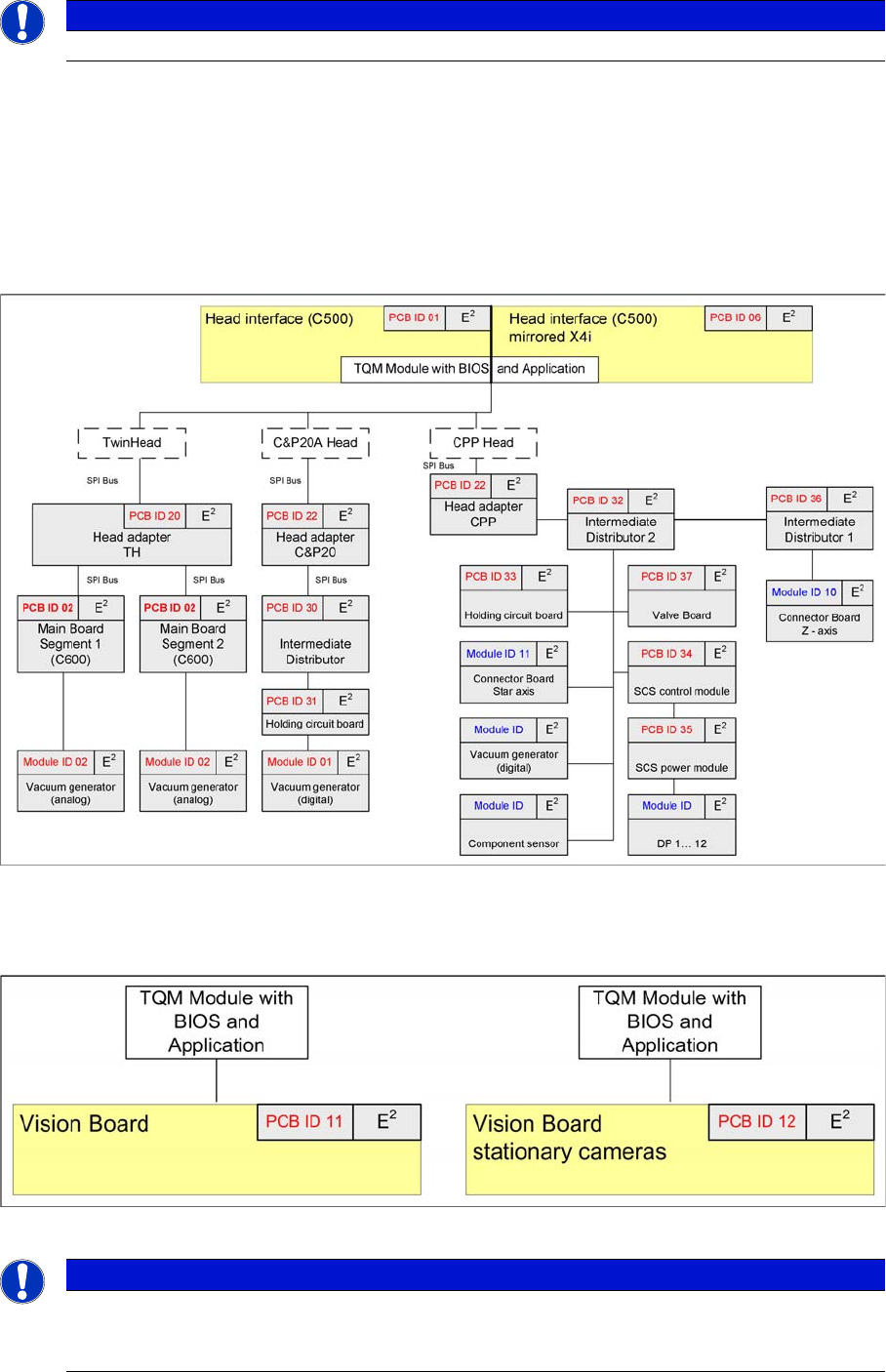
SIPLACE X series:
▪ Head interface (gantry 1 - 4)
▪ Head adapter (C&P20, C&P6/12, Twin head)
▪ Intermediate Distributor - C&P20
▪ Main board Twin Head
▪ Vision board (gantry 1 - 4)
▪ Illumination board stationary Cameras (Location 2/4)
▪ Vacuum sensor holding circuit board C&P20
Overview of board IDs, checked by the TQM module (SIPLACE X series and X4I with SW 70x)
▪ In X series machines with TQM, the PCB ID is read out of the BIOS.
▪ In X series machines with HCU, the PCB ID is read out of the application.
Board IDs for Vision boards (SIPLACE X)
NOTICE
The same PCB IDs apply for the SIPLACE X4I, even if head modularity is not possible.
NOTICE
The board ID for the Vision board (gantries 1 - 4), the illumination board for the stationary
cameras (sector 2/4) and the holding circuit vacuum sensor board for C&P20 are currently not
evaluated.
Communication and Control
Reading the Board IDs out of the EEPROM Board IDs
Student Guide SIPLACE X-Serie and X4I SW70x (AL2) 140
Reading the Board IDs ou t of the EEPROM
4.6.2 Reading the Board IDs out of the EEPROM
The board ID can be checked with the help of the Cacciatool.
You can use CAN Bus commands to read the board type IDs or open the corresponding menu to read
the memory of the EEPROM. When one or more ID‘s are missing so you can write the correct ID on the
board.
At the moment it is necessary to use the correct ID‘s on the board which are installed on the gantry (Head
interface, - adapter, Intermediate distributor and main board). The other board type ID‘s are not used at
the moment.
Reading Out the Board Type ID via the Grippe r Menu
4.6.2.1 Reading Out the Board Type ID via the Gripper Menu
► Switch off the machine.
► Connect the service laptop to the machine CAN bus at PA1 and/or PA2.
Make sure that the cable is connected at channel 1 for PA1 and at channel 2 for PA2 of the Kvaser
card.
► Switch on the machine
► Start the Caccia software and check the machine configuration in Caccia.
► Doubleclick on the Open Subsystem Control Center button.
Select Get Versions. All available subsystems will be shown with their firmware versions and their
CAN IDs.
► Select the head processor for the relevant gantry e.g. gantry 1.
► Open the GSMfolder.
CAUTION
Direct CAN bus commands should only be used by specially trained and qualified service
technicians.
NOTICE
When you want to be read out the board type ID‘s via the menu gripper, the BIOS and
application-software have to downloaded on the TQM module. Reading out is currently only
possible via the Gripper menu. to write the ID‘s on the EEPROM you need CAN Bus
commands.
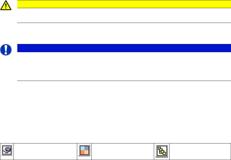
Change Properties Change Machine
Configuration
Open Subsystem Control
Center