00194614-08 Trainingsdoku. SG X-Serie_X4i SW70x (AL2)_EN.pdf - 第155页
Energy and Compressed Air Supply Power supply Power supp ly 155 Student Guide SIPLACE X-Serie and X4I SW70x (AL2) Main power supply 3 phase alternating p o wer is supplied for operation of the SIPL ACE X machines. N is o…
Energy and Compressed Air Supply
Subdistributor (X Series from Ma. No. B326) Power supply
Student Guide SIPLACE X-Serie and X4I SW70x (AL2) 154
Subdistributo r (X Series from Ma. No. B326)
5.2.3 Subdistributor (X Series from Ma. No. B326)
Power supply
5.2.4 Power supply
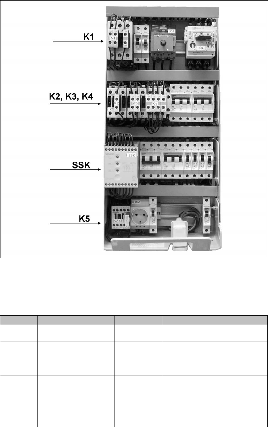
The main power supply unit is mounted on a compact slide-in module, and located on the left side of the
machine. When viewed from the outside only the red main power switch is visible.
A lockable door prevents access to the power supply.
With the open cover, the state of the following protective devices can be quite easily monitored.
▪ Motor Circuit Breaker
▪ Main contactor
▪ Safety relay
▪ Power circuit breaker
▪ Protective contactor combination (SSK)
The following work must be performed to adjust the power supply to the country-specific requirements
(see also the conversion instructions for power supplies):
1. Replace the motor protecting switch
2. Replace the power supply cable (country-specific)
3. At the primary end of transformer T1, the terminal connectors (U, V, W) must be reconnected to fulfill
the country-specific voltage requirements.
4. Reconnect the connector on the inrush limitation board transformer.
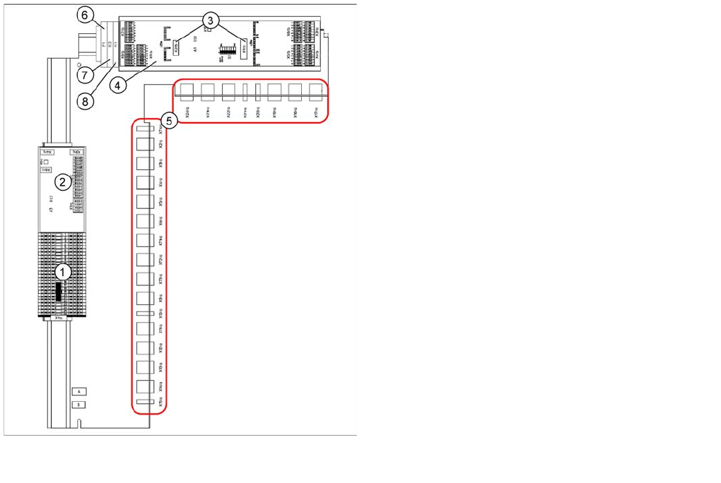
Subdistributor (X Series from Ma. No. B326, X4I)
[03046226-xx]
Legend:
1. Terminal strip X1ra (GND,+5 V,+15 V,-
15 V,+24 V,+52 V, various signals)
2. DC/DC distributor for illumination of all cameras
(PCB, component and stationary cameras) in
placement area 1
3. Socket for Interface 1-Wire CAT5
4. CAN I/O module (A1)
5. Connector block (connection X3ra - X6ra, X71ra-
X74ra, X10ra - X24ra)
6. F1: Fuse for hood fan
7. K3: Relay for hood fan
8. K1: This relay switches the main valve in the
pneumatic unit.
Energy and Compressed Air Supply
Power supply Power supply
155 Student Guide SIPLACE X-Serie and X4I SW70x (AL2)
Main power supply
3 phase alternating power is supplied for operation of the SIPLACE X machines. N is only used for the
service socket. The contacts L1/L2/L3/N/PE are below the main power module. The phase L3 is also
fuse-protected for the server socket, via the F1 fuse.
Voltages at the M ain Power Supply
5.2.4.1 Voltages at the Main Power Supply
Assembly Designation Contact Voltages
X100 Main power supply L1, L2, L3 3 x 204 VAC / 3 x 380 VAC
3 x 400 VAC / 3 x 415 VAC
X102 service socket L3, N, PE 115 VAC/220 VAC/
230 VAC/240 VAC
Z1 Main power filter L1, L2, L3 3 x 204 VAC / 3 x 380 VAC
3 x 400 VAC / 3 x 415 VAC
Q1 Main switch 1, 3, 5 &
2, 4, 6
3 x 204 VAC / 3 x 380 VAC
3 x 400 VAC / 3 x 415 VAC
Q2 Motor Circuit Breaker 1, 3, 5 &
2, 4, 6
3 x 204 VAC / 3 x 380 VAC
3 x 400 VAC / 3 x 415 VAC
L20 Discharge inductor L1, L2, L3 3 x 204 VAC / 3 x 380 VAC
3 x 400 VAC / 3 x 415 VAC

Energy and Compressed Air Supply
Power supply Power supply
Student Guide SIPLACE X-Serie and X4I SW70x (AL2) 156
K1 Main contactor 1, 3, 5 &
2, 4, 6
3 x 204 VAC / 3 x 380 VAC
3 x 400 VAC / 3 x 415 VAC
K2 Contactor switch on relay for
build up of voltage for the
intermediate circuit (X/Y/star
axes)
1, 3, 5 &
2, 4, 6
3 x 177 VAC
K3 Contactor switch on relay for
build up of voltage for the
intermediate circuit (X/Y/star
axes)
1, 3, 5 &
2, 4, 6
3 x 177 VAC
K4 Contactor switch on relay for
build up of voltage for the
intermediate circuit (X/Y/star
axes)
1, 3, 5, &.
2, 4, 6
3 x 177 VAC
K5 Contactor
(software release =
Software_EIN OK (software
is ON)
A1 (+) – A2 (-)
1, 3, 7 &.
2, 4, 8
24 VDC
24 VDC against GND
24 VDC against GND
K6 (SSK) Combination circuit breaker L+, X1, X3, X5
13, 33
23
24 VDC against GND
24 VDC against GND
32 VDC against GND
F1 Fuse (6 A)
service socket; 1-phase
1, 2 115 VAC / 220 VAC
230 VAC / 240 VAC
F2 Fuse(32 A)
changeover table; 3-phase
1, 3, 5 &
2, 4, 6
3 x 36 VAC
F4 Fuse (32 A)
X/Y axis; 3-phase.
1, 3, 5 &
2, 4, 6
3 x 177 VAC
F5 Fuse (10 A)
star axis; 1-phase
1, 2 145 VDC to GND
F6 Fuse (10 A)
Z and DP axis; DP motors
C&P20A (DC/DC converter
in the axis unit), 1-phase.
1, 2 39 VDC to GND
F7 Fuse (6 A)
secondary circuit; 3-phase
1, 3, 5 and
2, 4, 6
3 x 230 VAC
F8 Fuse (6 A)
board conveyor; 1-phase
1, 2 33 VDC to GND
F10 fuse (16A) rectifier V7 and
V70; 3-phase
1, 2 3 x 39 VAC
F11 Fuse (1A) inrush current
limitation board 1-phase
1, 2 33,6 VDC to GND
F12 Fuse (6 A)
illumination; 1-phase
1, 2 52 VDC to GND
F13 fuse (3A) monitor;
1-phase
1, 2 26 VDC to GND
F14 Fuse (6 A)
cooling device Y motor
1-phase
1, 2 24 VDC to GND
F21 / F22 /
F23
Micro fuse (T6,3A)
discharge inductor L20
1, 2 3 x 204 VAC / 3 x 380 VAC
3 x 400 VAC / 3 x 415 VAC
Assembly Designation Contact Voltages