00194614-08 Trainingsdoku. SG X-Serie_X4i SW70x (AL2)_EN.pdf - 第156页
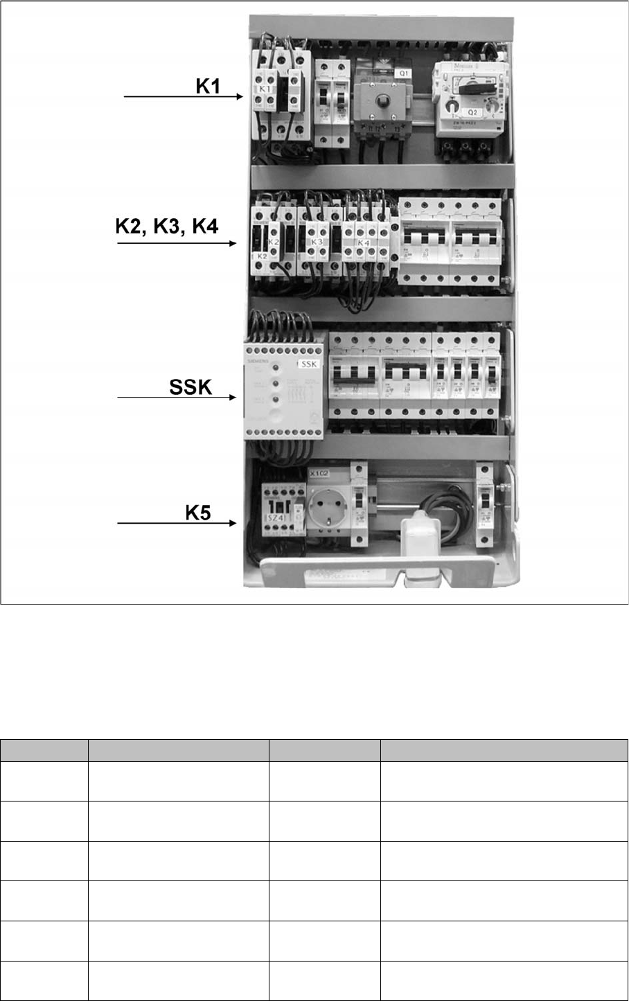
Energy and Compressed Air Supply Power supply Power supply Student Guide SIPLACE X-Serie and X4I SW70x (AL2) 156 K1 Main contactor 1, 3, 5 & 2, 4, 6 3 x 204 VAC / 3 x 380 VAC 3 x 400 VAC / 3 x 415 VAC K2 Contactor sw…
Energy and Compressed Air Supply
Power supply Power supply
155 Student Guide SIPLACE X-Serie and X4I SW70x (AL2)
Main power supply
3 phase alternating power is supplied for operation of the SIPLACE X machines. N is only used for the
service socket. The contacts L1/L2/L3/N/PE are below the main power module. The phase L3 is also
fuse-protected for the server socket, via the F1 fuse.
Voltages at the M ain Power Supply
5.2.4.1 Voltages at the Main Power Supply
Assembly Designation Contact Voltages
X100 Main power supply L1, L2, L3 3 x 204 VAC / 3 x 380 VAC
3 x 400 VAC / 3 x 415 VAC
X102 service socket L3, N, PE 115 VAC/220 VAC/
230 VAC/240 VAC
Z1 Main power filter L1, L2, L3 3 x 204 VAC / 3 x 380 VAC
3 x 400 VAC / 3 x 415 VAC
Q1 Main switch 1, 3, 5 &
2, 4, 6
3 x 204 VAC / 3 x 380 VAC
3 x 400 VAC / 3 x 415 VAC
Q2 Motor Circuit Breaker 1, 3, 5 &
2, 4, 6
3 x 204 VAC / 3 x 380 VAC
3 x 400 VAC / 3 x 415 VAC
L20 Discharge inductor L1, L2, L3 3 x 204 VAC / 3 x 380 VAC
3 x 400 VAC / 3 x 415 VAC

Energy and Compressed Air Supply
Power supply Power supply
Student Guide SIPLACE X-Serie and X4I SW70x (AL2) 156
K1 Main contactor 1, 3, 5 &
2, 4, 6
3 x 204 VAC / 3 x 380 VAC
3 x 400 VAC / 3 x 415 VAC
K2 Contactor switch on relay for
build up of voltage for the
intermediate circuit (X/Y/star
axes)
1, 3, 5 &
2, 4, 6
3 x 177 VAC
K3 Contactor switch on relay for
build up of voltage for the
intermediate circuit (X/Y/star
axes)
1, 3, 5 &
2, 4, 6
3 x 177 VAC
K4 Contactor switch on relay for
build up of voltage for the
intermediate circuit (X/Y/star
axes)
1, 3, 5, &.
2, 4, 6
3 x 177 VAC
K5 Contactor
(software release =
Software_EIN OK (software
is ON)
A1 (+) – A2 (-)
1, 3, 7 &.
2, 4, 8
24 VDC
24 VDC against GND
24 VDC against GND
K6 (SSK) Combination circuit breaker L+, X1, X3, X5
13, 33
23
24 VDC against GND
24 VDC against GND
32 VDC against GND
F1 Fuse (6 A)
service socket; 1-phase
1, 2 115 VAC / 220 VAC
230 VAC / 240 VAC
F2 Fuse(32 A)
changeover table; 3-phase
1, 3, 5 &
2, 4, 6
3 x 36 VAC
F4 Fuse (32 A)
X/Y axis; 3-phase.
1, 3, 5 &
2, 4, 6
3 x 177 VAC
F5 Fuse (10 A)
star axis; 1-phase
1, 2 145 VDC to GND
F6 Fuse (10 A)
Z and DP axis; DP motors
C&P20A (DC/DC converter
in the axis unit), 1-phase.
1, 2 39 VDC to GND
F7 Fuse (6 A)
secondary circuit; 3-phase
1, 3, 5 and
2, 4, 6
3 x 230 VAC
F8 Fuse (6 A)
board conveyor; 1-phase
1, 2 33 VDC to GND
F10 fuse (16A) rectifier V7 and
V70; 3-phase
1, 2 3 x 39 VAC
F11 Fuse (1A) inrush current
limitation board 1-phase
1, 2 33,6 VDC to GND
F12 Fuse (6 A)
illumination; 1-phase
1, 2 52 VDC to GND
F13 fuse (3A) monitor;
1-phase
1, 2 26 VDC to GND
F14 Fuse (6 A)
cooling device Y motor
1-phase
1, 2 24 VDC to GND
F21 / F22 /
F23
Micro fuse (T6,3A)
discharge inductor L20
1, 2 3 x 204 VAC / 3 x 380 VAC
3 x 400 VAC / 3 x 415 VAC
Assembly Designation Contact Voltages
Energy and Compressed Air Supply
Power supply Power supply
157 Student Guide SIPLACE X-Serie and X4I SW70x (AL2)
Input Voltage
5.2.4.2 Input Voltage
Input voltage
Legend
Transform er 1
5.2.4.3 Transformer 1
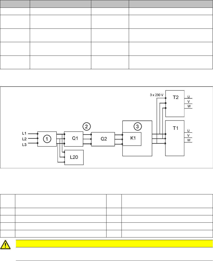
The main reason for the transformer T1 is to power the X/Y and star axis, protected by F4. Contactors
K2, K3 and K4 illustrate fixed elements of the electrical safety concept. In a fault event, e.g. open cover,
the servos are disconnected from the energy.
Primary Transformer T1
▪ 250 VDC for the servo amplifiers of the x and y axes.
▪ 150 VDC servo amplifiers of the star axis.
▪ 34 VDC for the inrush current limiter servo
▪ 52 VDC for the DC/DC converters in the main power unit
▪ 48 VDC for DC/DC converter of camera illumination and the computer unit
F61 / F62 fuse (10A) rectifier U4 1, 2 3 x 28 VAC
F81 / F82 Microfuse (T10A)
rectifier U5
1, 2 3 x 23.8 VAC
F111 / F112 Microfuse (T1A)
rectifier U8
1, 2 3x 25.7 (23.8V) VAC
F131 / F132 Microfuse (T4A)
rectifier U10
1, 2 3x 20.5 (19.7V) VAC
F141 / F142 Microfuse (T6,3A)
rectifier U11
1, 2 3x 18.9 (18.7V) VAC
Assembly Designation Contact Voltages
1 Current filter K1 main contactor and inrush current limiter for
T1
2 3 phases T1 transformer 1
3 Inrush current limitation board for T1 T2 Transformer 2
Q1 Main switch L20 Discharge inductor
Q2 Motor Circuit Breaker
CAUTION
After transformers T1 and T2, the main power potential ends and the machine is only fed by
secondary voltages.