00194614-08 Trainingsdoku. SG X-Serie_X4i SW70x (AL2)_EN.pdf - 第158页
Energy and Compressed Air Supply Power supply Power supply Student Guide SIPLACE X-Serie and X4I SW70x (AL2) 158 Overview of main voltage supply an d transformer Transform er T2 5.2.4.4 Transformer T2 The main task assum…
Energy and Compressed Air Supply
Power supply Power supply
157 Student Guide SIPLACE X-Serie and X4I SW70x (AL2)
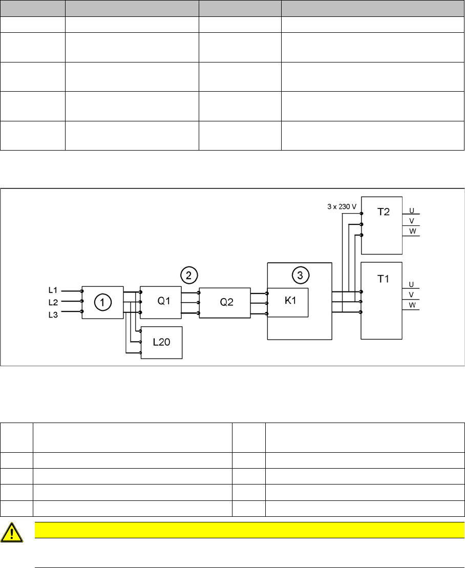
Input Voltage
5.2.4.2 Input Voltage
Input voltage
Legend
Transform er 1
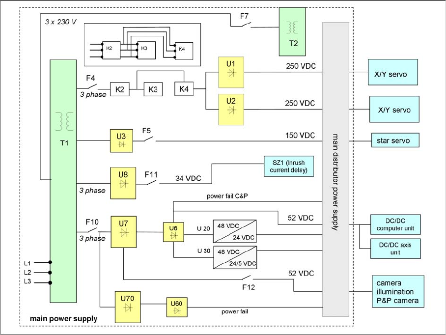
5.2.4.3 Transformer 1
The main reason for the transformer T1 is to power the X/Y and star axis, protected by F4. Contactors
K2, K3 and K4 illustrate fixed elements of the electrical safety concept. In a fault event, e.g. open cover,
the servos are disconnected from the energy.
Primary Transformer T1
▪ 250 VDC for the servo amplifiers of the x and y axes.
▪ 150 VDC servo amplifiers of the star axis.
▪ 34 VDC for the inrush current limiter servo
▪ 52 VDC for the DC/DC converters in the main power unit
▪ 48 VDC for DC/DC converter of camera illumination and the computer unit
F61 / F62 fuse (10A) rectifier U4 1, 2 3 x 28 VAC
F81 / F82 Microfuse (T10A)
rectifier U5
1, 2 3 x 23.8 VAC
F111 / F112 Microfuse (T1A)
rectifier U8
1, 2 3x 25.7 (23.8V) VAC
F131 / F132 Microfuse (T4A)
rectifier U10
1, 2 3x 20.5 (19.7V) VAC
F141 / F142 Microfuse (T6,3A)
rectifier U11
1, 2 3x 18.9 (18.7V) VAC
Assembly Designation Contact Voltages
1 Current filter K1 main contactor and inrush current limiter for
T1
2 3 phases T1 transformer 1
3 Inrush current limitation board for T1 T2 Transformer 2
Q1 Main switch L20 Discharge inductor
Q2 Motor Circuit Breaker
CAUTION
After transformers T1 and T2, the main power potential ends and the machine is only fed by
secondary voltages.
Energy and Compressed Air Supply
Power supply Power supply
Student Guide SIPLACE X-Serie and X4I SW70x (AL2) 158
Overview of main voltage supply and transformer
Transform er T2
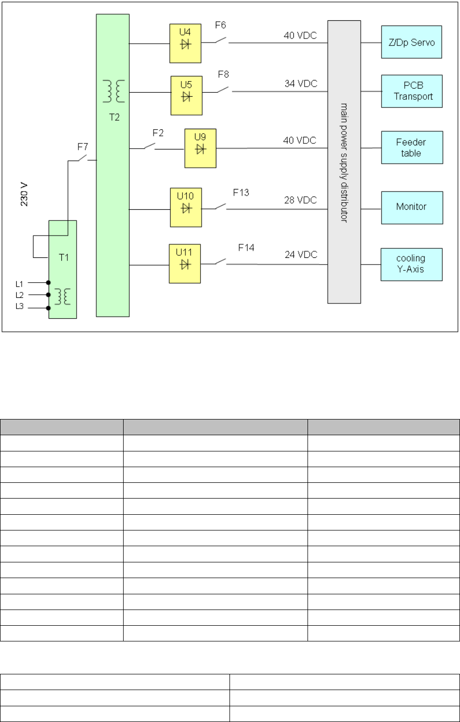
5.2.4.4 Transformer T2
The main task assumed by transformer T2 is to power the Z and DP servos, protected by F6.
Secondary transformer T2
▪ 40 VDC for the servo amplifiers the z and dp axes.
▪ 34 VDC for PCB handling system.
▪ 40 VDC for the component tables (30 V for feeder operation).
▪ 10 VDC for the component tables (5 V for logic).
▪ 28 VDC for the monitor.
▪ 24 VDC for cooling the Y axis motor. (motor generating compressed air)
Energy and Compressed Air Supply
Power supply Power supply
159 Student Guide SIPLACE X-Serie and X4I SW70x (AL2)
Overview transformer 2
Voltages in the Power Supply U nit After Switc hing On
5.2.4.5 Voltages in the Power Supply Unit After Switching On
When the main switch is switched on, the following voltages are generated and may or may not be
switched (enabled, not enabled) through to the modules:
Voltages for the service socket
Voltages Module State
250 VDC X/Y servo unit not enabled
150 VDC servo unit not enabled
34 VDC PCB handling system not enabled
24 VDC tape cutter not enabled
34 VDC SZ1 main power inrush current enabled
52 VDC DC/DC converter main power supply enabled
48 VDC Illumination for all cameras enabled
52 VDC Supply to power fail board enabled
40 VDC Z/DP axes enabled
40 VDC Changeover table enabled
28 VDC monitor enabled
24 VDC fan enabled
230 or 115 or 240 VAC Service socket Independent of the main switch
230 VAC (Europe) Input 3 x 400 VAC
115 VAC (U. S. A.) Input 3 x 204 VAC
130 VAC (other) Input 3 x 230 VAC