00194614-08 Trainingsdoku. SG X-Serie_X4i SW70x (AL2)_EN.pdf - 第165页
Energy and Compressed Air Supply Power supply Safety and Signaling Circuit 165 Student Guide SIPLACE X-Serie and X4I SW70x (AL2) Safety loop Description of emergency STOP circuit: When t he emergency STOP circuit is clos…
Energy and Compressed Air Supply
Safety and Signaling Circuit Power supply
Student Guide SIPLACE X-Serie and X4I SW70x (AL2) 164
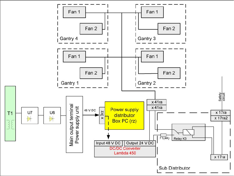
Voltage Supply for Hood Fans
The fans are supplied with 24V from the computer unit by the DC/DC converter and are switched via the
safety circuit.
Safety and Si gnaling Circuit
5.2.8 Safety and Signaling Circuit
Emergency STOP Circuit (Safety Circuit)
5.2.8.1 Emergency STOP Circuit (Safety Circuit)
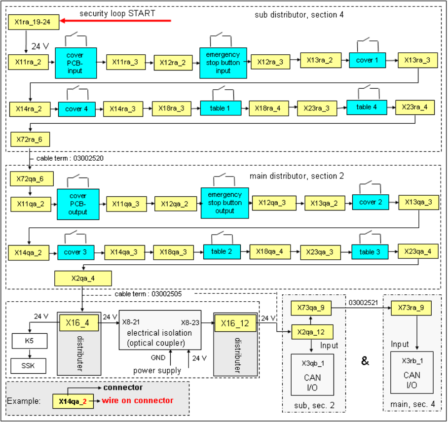
Following contacts are switched in serial and build the safety loop:
▪ 4 protective cover switches (main cover).
▪ conveyor cover switch.
▪ Contact on changeover table
▪ The emergency STOP button may not be pressed (input and output conveyors)
Energy and Compressed Air Supply
Power supply Safety and Signaling Circuit
165 Student Guide SIPLACE X-Serie and X4I SW70x (AL2)
Safety loop
Description of emergency STOP circuit:
When the emergency STOP circuit is closed, there is 24 V present at K5, contact 3. A further 24 V signal
is sent as EMERGENCY STOP loop OK Sent to each CAN I/O module, indicating that the covers are all
closed and that the changeover tables are connected.
Energy and Compressed Air Supply
Safety and Signaling Circuit Power supply
Student Guide SIPLACE X-Serie and X4I SW70x (AL2) 166
Control Loops
5.2.8.2 Control Loops
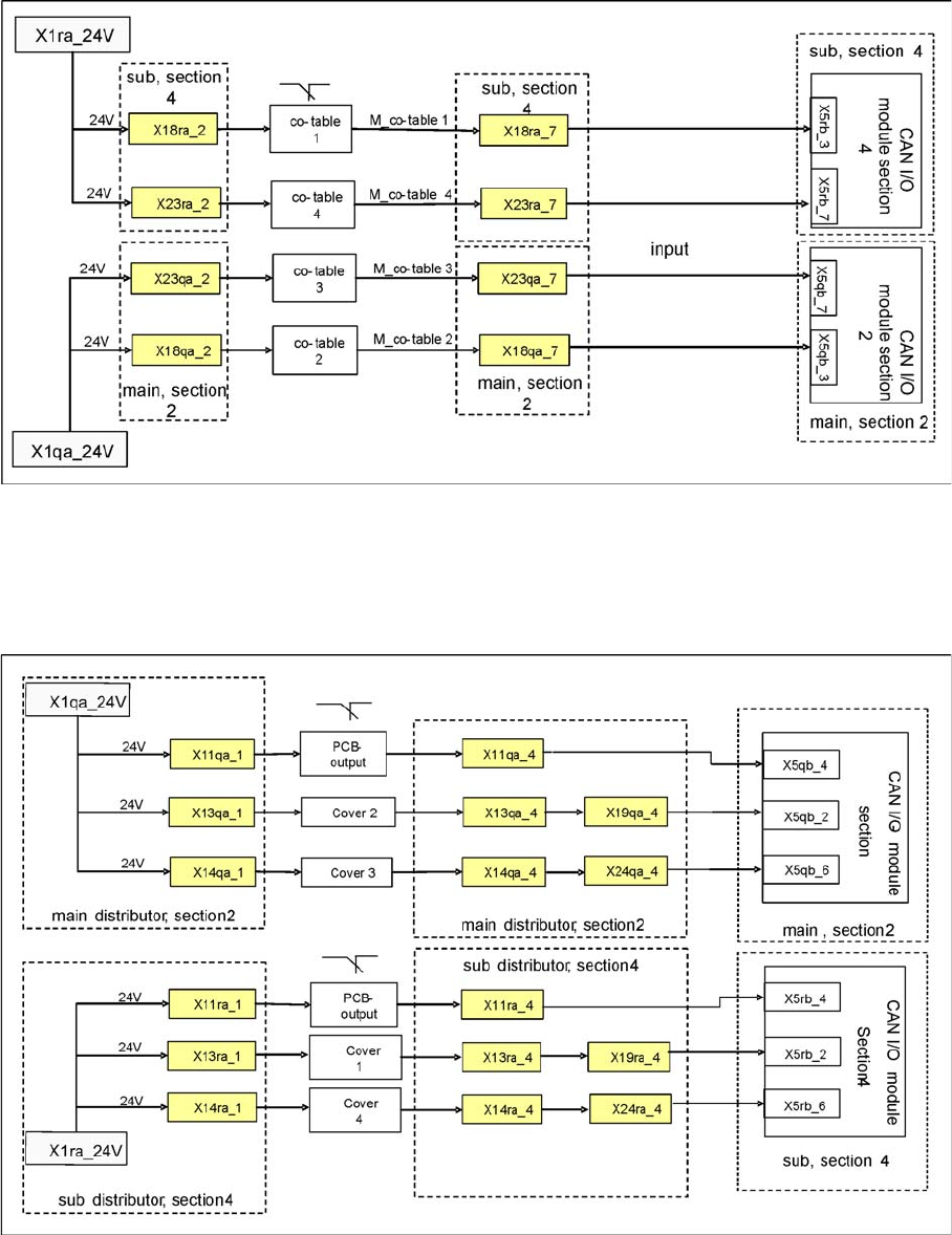
Changeover Table Loop
Changeover Table Loop
Changeover table loop
The 4 component tables are switched in parallel mode. If one or more tables are not connected, the
contact will close and 24 V will be present at the input of the CAN I/O module in sector 2 or 4.
Cover Control Loop
Cover Control Loop
Cover Control Loop
The cover control loop consists of 6 contacts (2 main covers, each with 2 contacts and 2 covers on the
conveyors (input and output)), which are switched in parallel mode. If 1 or more covers are open, the
contact will close and the 24 V will be present at the input of the CAN I/O module in sector 4. The same
applies to sector 2. This shows that one of the covers is open.