00194614-08 Trainingsdoku. SG X-Serie_X4i SW70x (AL2)_EN.pdf - 第168页
Energy and Compressed Air Supply Protective Contactor Combination K6 (SSK) Power supply Student Guide SIPLACE X-Serie and X4I SW70x (AL2) 168 How Does the Emergency STOP Circ uit Funct ion? 5.2.8.3 How Does the Emergency…
Energy and Compressed Air Supply
Power supply Safety and Signaling Circuit
167 Student Guide SIPLACE X-Serie and X4I SW70x (AL2)
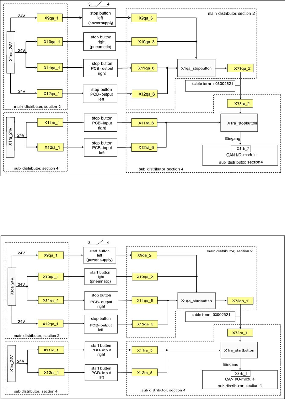
Stop But ton Loop
Stop Button Loop
Stop Button Loop
The stop button loop consists of 6 contacts which are switched in parallel mode. If one or more STOP
buttons has been pressed, the contact will close and 24 V will be present at the input of the CAN I/O
module in sector 4, showing that one of the STOP buttons has been pressed.
Start Bu tton Loop
Start Button Loop
Start Button Loop
The start button loop consists of 6 contacts and they are switched in parallel mode. If one or more START
buttons has been pressed, the contact will close and the 24 V will be present at the input of the CAN I/
O module in sector 4, showing that one of the START buttons has been pressed.
Energy and Compressed Air Supply
Protective Contactor Combination K6 (SSK) Power supply
Student Guide SIPLACE X-Serie and X4I SW70x (AL2) 168
How Does the Emergency STOP Circ uit Funct ion?
5.2.8.3 How Does the Emergency STOP Circuit Function?
The placement system cannot be used in placement mode until all the supply voltages have been
enabled by the protective contactor combination.
The following conditions must also be fulfilled:
▪ All four component changeover tables must be docked.
▪ All covers must be closed.
▪ Both emergency stop buttons must be released.
▪ The minimum air pressure must be present.
▪ The software enable signal must be ready.
▪ The message Safety loop OK Must be sent (for GND on X6 on SSK, CAN I/O output)
▪ 24 V must be present at the START button.
After pressing the start button, the protective contactor combination releases the following voltages:
▪ Secondary circuit 250 V for servo X/Y axis (via K2, K3, K4).
▪ Secondary circuit 150 V for star axis.
▪ The servo unit receives the servo release signal for the servo amplifier (K4.5)
▪ The message Ctrl_On must be issued at CAN I/O (24 V from the axis unit after receiving the
servo release signal)
▪ 34 V operating voltage for the transport handling.
▪ 24 V operating voltage for the tape cutter.
▪ M_X/Y: +24 V for K3 and K4
▪ M_tape cutter: +24 V for K2
Protective Conta ctor Combinatio n K6 (SSK)
5.2.9 Protective Contactor Combination K6 (SSK)
Energy and Compressed Air Supply
Power supply Protective Contactor Combination K6 (SSK)
169 Student Guide SIPLACE X-Serie and X4I SW70x (AL2)
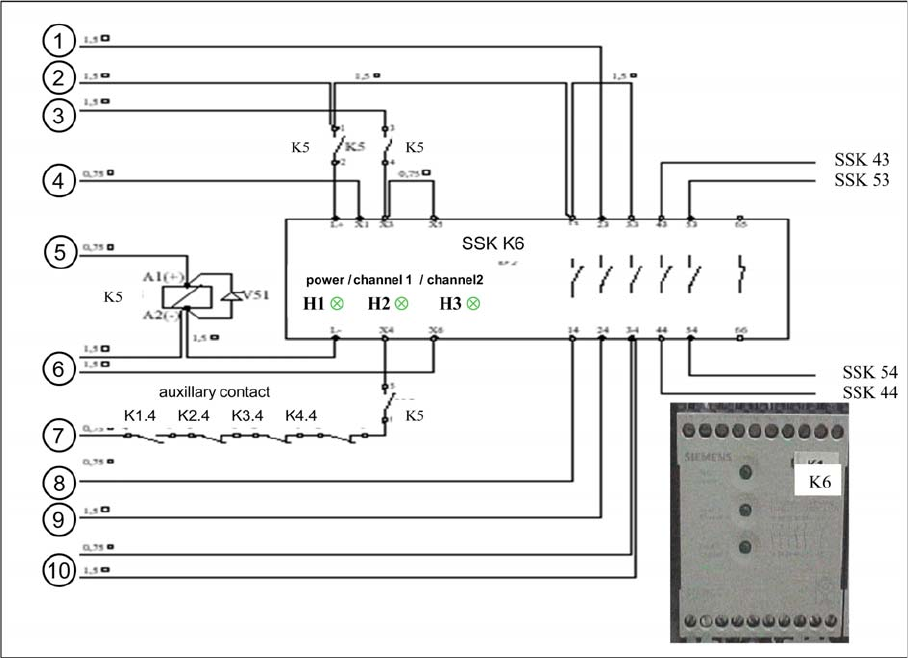
Legend:
1. Power for transport 34 VDC from T2
2. Power 24 VDC input from power supply DC/DC converter.
3. 24 VDC input from emergency STOP circuit
4. Message READY to CAN I/O module (SSK is OK.)
5. Software release (24 VDC when start button pressed and SW release signal is given).
6. GND for SSK (X6), from message Safety loop OK
7. Start button pressed (24 VDC form start button).
8. M_X/Y: 24 VDC from SSK (power for K3 and K4).
9. Power for transport 34 VDC from SSK
10. M_tape cutter: 24 VDC for contactor K2 and power for tape cutter (24 VDC)
About SSK K6
5.2.9.1 About SSK K6
Contactor K6 is an industry standard safety combination contactor. Internally it consists of 3 relays which
are configured in a complex fashion to give maximum protection in a fail safe mode. Unfortunately, for
ease of understanding, these internal relays are labeled K1', K2' & K3'. The status of the contactor is
indicated by LEDs labeled as H1, H2 and H3.
When the contactor is in an energized state internal relays K2' and K3' are energized, relay K1' is de-
energized. This status closes the contacts 13 and 14, 23 and 24, 33 and 34.
When this status is achieved, K6 is "ON" and the 3 LEDs H1, H2 and H3 all shine.
How is SSK K6 Energi zed?
5.2.9.2 How is SSK K6 Energized?
If the covers and the emergency STOP circuit are closed and K5 is deactivated, 24 V will be supplied to
terminals X1, X3 and X4, as soon as the GND is present at contact 6 (X6) - a state triggered by the
message Safety loop OK - and the start button has been pressed. This voltage allows K1 to be
energized and when its contacts close, K2 and K3 will energize. As soon as these contacts energize, K1
is de-energized. However K2 and K3 remain energized as their contacts have a self latching facility.
Pressing the ON Button
5.2.9.3 Pressing the ON Button
Assuming the ON button is pressed: 24 V is activated and will split into 2 paths.
▪ 1. : 24V is activated at the CAN I/O module 1. The signal from this module activates the CAN bus to
notify the machine controller that the ON button has been pressed. This deactivates the message
Press Start Key .
▪ 2. : 24V is present at the power supply main distributor X16_2 and, from here, this signal (start
button) is sent to K1.4 (closed when main switch ON), K2.4 (break contact, NC), K3.4 (break contact,
NC), K4.4 (break contact, NC), K5 (make contact, NO), ending at pin 6 of the SSK. The 24 V is
activated when the following conditions are met:
Condition: When the machine controller gets the signal (1st path) START BUTTON pressed , it will set
an output via the CAN I/O module and supply A1 of contactor K5 with 24V (C_Software_On)
So when K5 is energized, the signal from 2nd path will flow to X4 of the SSK.
How Does the Protective C ontacto r Combination (S SK) Latch ?
5.2.9.4 How Does the Protective Contactor Combination (SSK) Latch?
Condition: When K5 is energized, the following will happen:
▪ L+ will get 24 V and will light up the first LED
▪ Since L+ and X1 are internally connected, this 24 V signal will be fed back from X1 to the CAN I/O
module as a SSK READY.