00194614-08 Trainingsdoku. SG X-Serie_X4i SW70x (AL2)_EN.pdf - 第172页
Energy and Compressed Air Supply Power Distributio n Power supply Student Guide SIPLACE X-Serie and X4I SW70x (AL2) 172 Path 1: from X1 8, at section 2, X3qa, to te rminal strip X1qa an d then to the DC/DC converter Visi…
Energy and Compressed Air Supply
Power supply Power Distribution
171 Student Guide SIPLACE X-Serie and X4I SW70x (AL2)
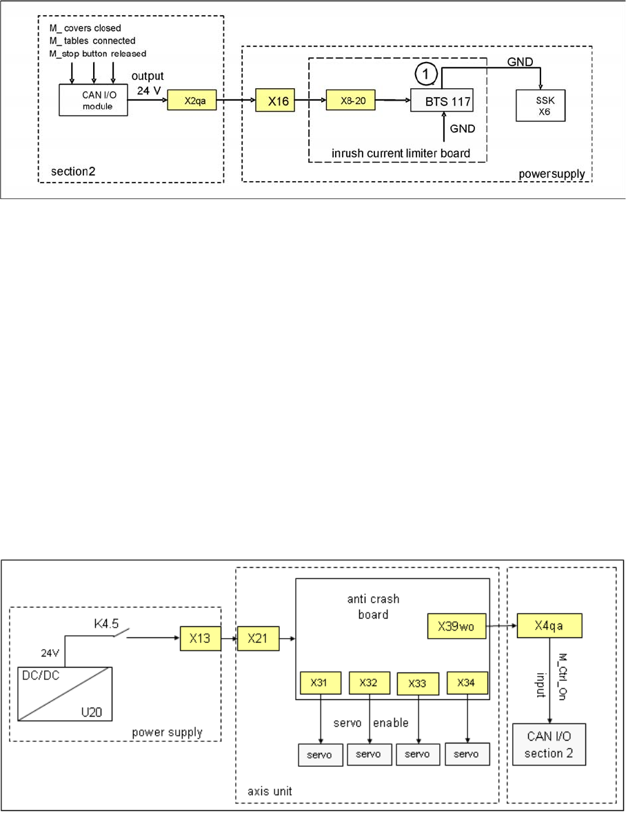
Signal safety loop
Legend:
1. BTS 117: voltage switch for GND
This signal is transmitted to the power supply X8-20 and connects GND to SSK, contact X6.
Control On Signal
5.2.10.3 Control On Signal
If connector K4 of the power supply is enabled, the auxiliary contact K4.5 will close and 24 V (servo
release signal) will be present from the DC/DC converter to the distributor of the main power supply X13,
to the axis unit X21 and to the anti-crash board.
The introduction of the A364 also involved direct software realization of the anti-crash function on the
axis card.
Here it is split in 2 paths:
Path 1: 24 V present as Servo enable signal at the X/Y axis servo board, to enable the servo
amplifier (to switch GND to the servo board via optical coupler).
Path 2: 24 V present as Ctrl_ON signal at sector 2, connector X4qa and ends as M_Ctrl_On at the CAN
I/O module. The 4 main axis is allowed to move now into any position.
Control On signal
Power Distribution
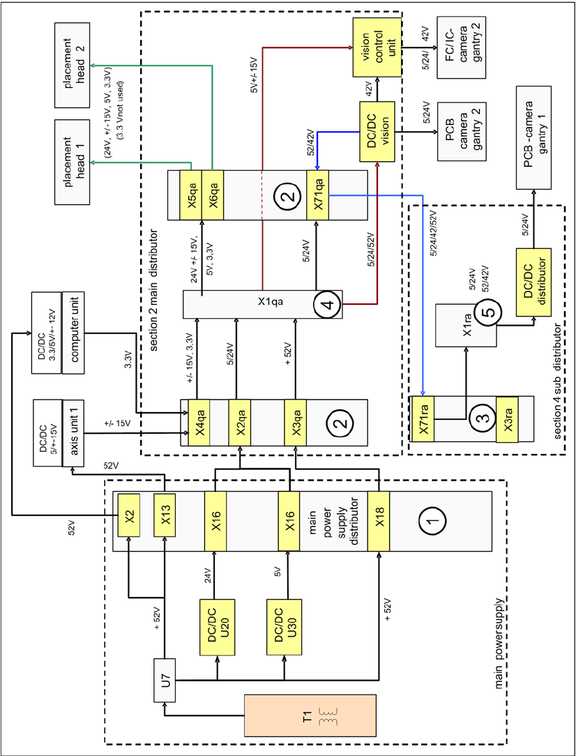
5.2.11 Power Distribution
The power distribution to the different sectors, gantries and heads is highly structured. 5V and 24 V,
generated by DC/DC converter U20 and U30 in main power supply, will first activate at distributor main
power supply, connector X16. Then at section 2, main distributor, connector X2qa and then at the
terminal block X1qa for general use, at connector X71qa and at last at connector X71ra, section 4.
52 V for camera illumination, generated by U7, is activated at main power supply distributor, X18, and
split into two paths.
Energy and Compressed Air Supply
Power Distribution Power supply
Student Guide SIPLACE X-Serie and X4I SW70x (AL2) 172
Path 1: from X18, at section 2, X3qa, to terminal strip X1qa and then to the DC/DC converter Vision for
converting the 42 V needed for the IC/FC camera illumination. The voltage is also present via connector
X71qa to connector X71ra in sector 4 and to X1ra, ending at the DC/DC distributor Vision (42V are not
used here).
Path 2: (this path is currently not used) from X18 at sector 2, X3ra, to terminal strip X1ra and then to the
DC/DC distributor Vision for converting the 42 V needed for IC/FC camera illumination in this sector.
The voltage supply +/-15 V is generated at the power pack in the axis unit from the 52 V and is then
present at X4qa, at the terminal strip X1qa, for general distribution and use. The voltage is then present
via X74qa to X74ra in sector 4 to the intermediate distributor (not shown in the following diagram).
power distribution
Energy and Compressed Air Supply
Pneumatic System Pneumatic Unit
173 Student Guide SIPLACE X-Serie and X4I SW70x (AL2)
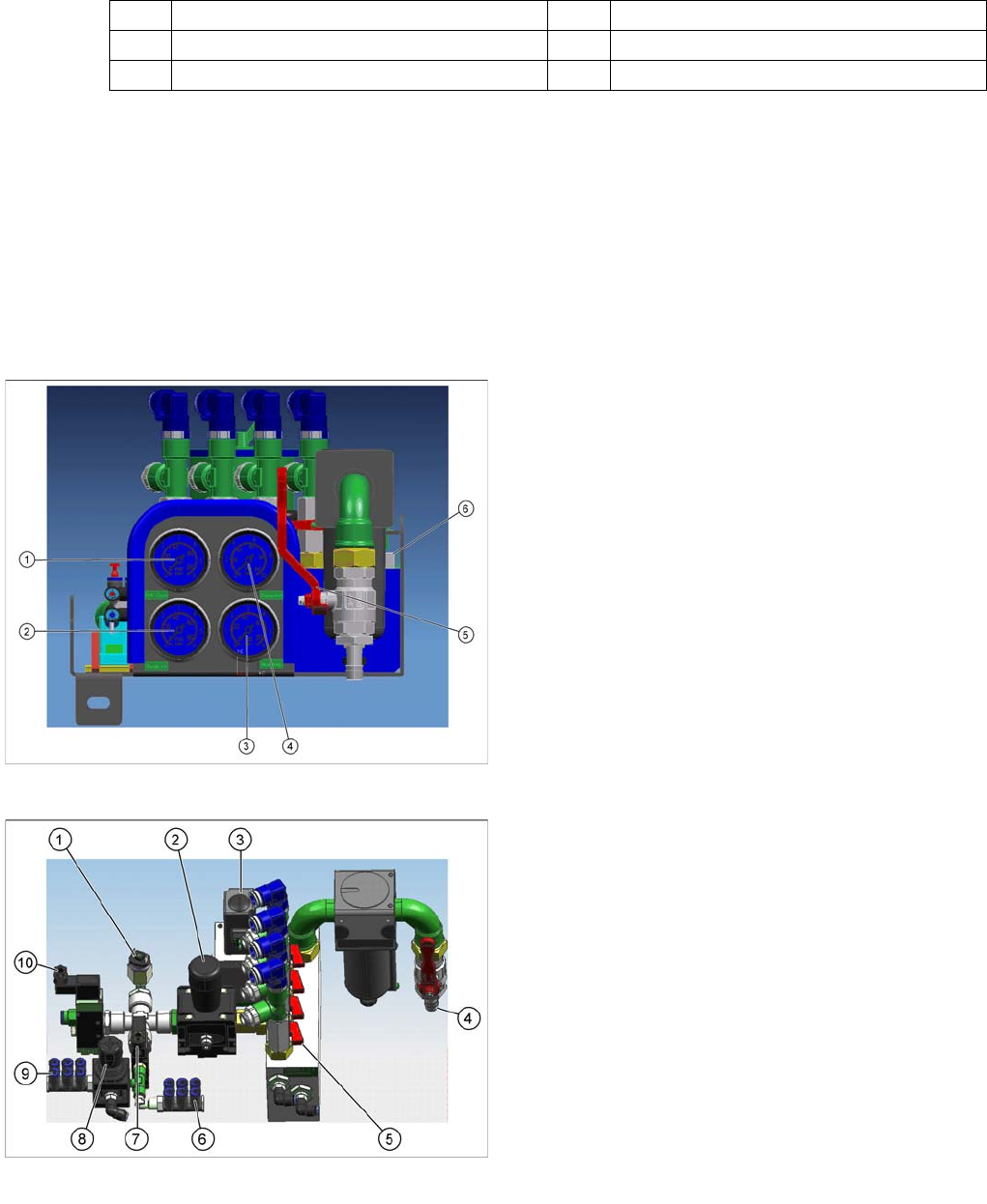
Legend
Pneumatic System
5.3 Pneumatic System
Pneumatic Unit
5.3.1 Pneumatic Unit
The pneumatic unit is mounted on a compact slide-in module, and located on the right side of the middle
section. A lockable door prevents access to the unit, which contains the whole compressed air supply
as required for the machine and its options. The pneumatic unit also contains the conveyor control, which
assumes control of PCB transportation in the machine and to the upstream and downstream stations.
(see Chapter Conveyor)
1 Main distributor voltage supply 4 Terminal strip X1qa sector 2
2 Connections – main distributor sector 2 5 Terminal strip X1ra sector 4
3 Subdistributor sector 4
Pneumatic Unit
Legend
1. Manometer 2.5 bar for bulkcase or nozzle changer
DLM
2. Manometer for gantries 4.8 bar
3. Manometer for machine components 5 bar (docking
unit, conveyor, cutter, NC C&P20)
4. Manometer for input pressure, min. 5 bar
5. Main shutoff valve
6. New air filter - air filter housing of metal with bayonet
connection and filling level display
Pneumatic Unit
Legend
1. Pressure sensor
2. Manual regulator for cutters and machine
components
3. Proportional valve
4. Main compressed air connection (5-10 bar)
5. Gantry distributor with shutoff valves for each gantry
6. 5 bar connections for docking unit or nozzle changer
C&P20
7. Main valve for machine components
8. Manual regulator for 2.5 bar bulkcase
9. 2.5 bar connections for bulkcase or NC C&P6/12
10. Safety valve for cutters