00194614-08 Trainingsdoku. SG X-Serie_X4i SW70x (AL2)_EN.pdf - 第173页
Energy and Compressed Air Supply Pneumatic System Pneumatic Unit 173 Student Guide SIPLACE X-Serie and X4I SW70x (AL2) Legend Pneumatic Syst em 5.3 Pneumatic System Pneuma tic Uni t 5.3.1 Pneumatic Unit The pneumatic uni…
Energy and Compressed Air Supply
Power Distribution Power supply
Student Guide SIPLACE X-Serie and X4I SW70x (AL2) 172
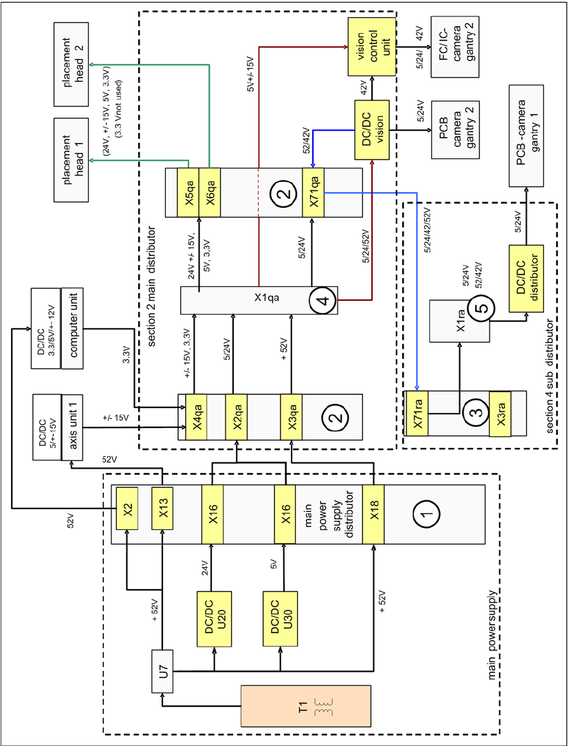
Path 1: from X18, at section 2, X3qa, to terminal strip X1qa and then to the DC/DC converter Vision for
converting the 42 V needed for the IC/FC camera illumination. The voltage is also present via connector
X71qa to connector X71ra in sector 4 and to X1ra, ending at the DC/DC distributor Vision (42V are not
used here).
Path 2: (this path is currently not used) from X18 at sector 2, X3ra, to terminal strip X1ra and then to the
DC/DC distributor Vision for converting the 42 V needed for IC/FC camera illumination in this sector.
The voltage supply +/-15 V is generated at the power pack in the axis unit from the 52 V and is then
present at X4qa, at the terminal strip X1qa, for general distribution and use. The voltage is then present
via X74qa to X74ra in sector 4 to the intermediate distributor (not shown in the following diagram).
power distribution
Energy and Compressed Air Supply
Pneumatic System Pneumatic Unit
173 Student Guide SIPLACE X-Serie and X4I SW70x (AL2)
Legend
Pneumatic System
5.3 Pneumatic System
Pneumatic Unit
5.3.1 Pneumatic Unit
The pneumatic unit is mounted on a compact slide-in module, and located on the right side of the middle
section. A lockable door prevents access to the unit, which contains the whole compressed air supply
as required for the machine and its options. The pneumatic unit also contains the conveyor control, which
assumes control of PCB transportation in the machine and to the upstream and downstream stations.
(see Chapter Conveyor)
1 Main distributor voltage supply 4 Terminal strip X1qa sector 2
2 Connections – main distributor sector 2 5 Terminal strip X1ra sector 4
3 Subdistributor sector 4
Pneumatic Unit
Legend
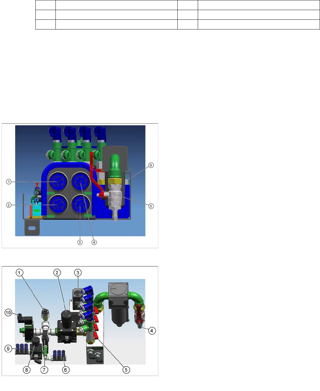
1. Manometer 2.5 bar for bulkcase or nozzle changer
DLM
2. Manometer for gantries 4.8 bar
3. Manometer for machine components 5 bar (docking
unit, conveyor, cutter, NC C&P20)
4. Manometer for input pressure, min. 5 bar
5. Main shutoff valve
6. New air filter - air filter housing of metal with bayonet
connection and filling level display
Pneumatic Unit
Legend
1. Pressure sensor
2. Manual regulator for cutters and machine
components
3. Proportional valve
4. Main compressed air connection (5-10 bar)
5. Gantry distributor with shutoff valves for each gantry
6. 5 bar connections for docking unit or nozzle changer
C&P20
7. Main valve for machine components
8. Manual regulator for 2.5 bar bulkcase
9. 2.5 bar connections for bulkcase or NC C&P6/12
10. Safety valve for cutters
Energy and Compressed Air Supply
Pneumatic Unit Pneumatic System
Student Guide SIPLACE X-Serie and X4I SW70x (AL2) 174
The input pressure (5-10 bar) flows through the compressed air filter. These need to be checked and
serviced at regular intervals. (see maintenance guide)
The compressed air is divided between two main paths via the compressed air distributor.
▪ Path 1: Compressed air supply to placement heads
▪ Path 2: Compressed air supply to machine components
▪ Path 1: All 4 gantries (placement heads are supplied with constant compressed air of 4.8 bar via the
proportionate valve.
▪ Path 2: The pressure for the machine components is set with a manual regulator to 5.0 +/-0.5 bar,
after the compressed air distributor. Afterwards, this path divides into three other paths.
– Path 2.1 This path supplies the docking units and the nozzle changer of the C&P20A head
directly with the 5.0 bar set at the manual regulator, via an electronic valve.
– Path 2.2 This path branches off after the electronic valve and the pressure is reduced via a
manual regulator to 2.5 +/-0.5 bar, for the bulkcase feeder option and the nozzle changers of the
C&P6/12 heads. (not X4I)
– Path 2.3 is switched via a safety valve and supplies 5.0 bar, set with a manual regulator, for the
conveyor and the cutters.
The input pressure and all pressures which can be set can also be controlled via manometers.
Pneumatic Unit
Legend
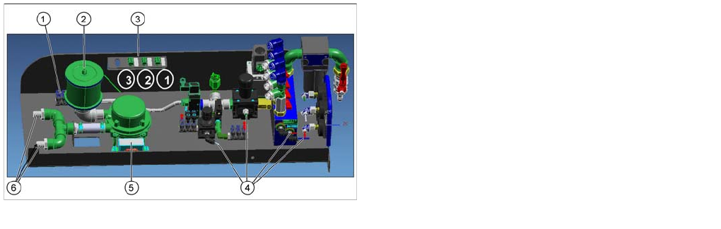
1. Distributor for cutters and conveyor
2. Suction filter for compressed air generator (cooling
the Y axes)
3. Connector 1-> X59: Main valve and pressure sensor
Connector 2-> X60: safety valve for cutter, conveyor
Connector 3-> X58: Proportional valve
4. Compressed air hoses to the manometers
5. Startup control for compressed air generator
6. Output compressed air generator 2.5 bar