00194614-08 Trainingsdoku. SG X-Serie_X4i SW70x (AL2)_EN.pdf - 第184页
Energy and Compressed Air Supply Cooling the Y Axis Motors for Placement Area 1/2 Room for Your Sketches and Notes Student Guide SIPLACE X-Serie and X4I SW70x (AL2) 184

Energy and Compressed Air Supply
Room for Your Sketches and Notes Cooling the Y Axis Motors for Placement Area 1/2
183 Student Guide SIPLACE X-Serie and X4I SW70x (AL2)
Room for You r Sketches and Notes
5.4 Room for Your Sketches and Notes

Energy and Compressed Air Supply
Cooling the Y Axis Motors for Placement Area 1/2 Room for Your Sketches and Notes
Student Guide SIPLACE X-Serie and X4I SW70x (AL2) 184
Gantry
Overview Mechanical Structure of X and Y Axes
185 Student Guide SIPLACE X-Serie and X4I SW70x (AL2)
Gantry
6Gantry
Overview
6.1 Overview
The gantries of the SIPLACE X machines consist of one X and one Y axis. Both axes are driven by a
linear motor which is equipped with an integrated temperature sensor. These temperature sensors only
monitor the motor coils. Viewed from the direction of transport, the Y motors move from the right to the
left, in a more positive direction (new coordinate system) and the X motors move from the input conveyor
to the output conveyor, in a more positive direction. The coordinate origin is exactly in the center of the
machine. The placement heads are mounted on the head plates of the respective X axis.
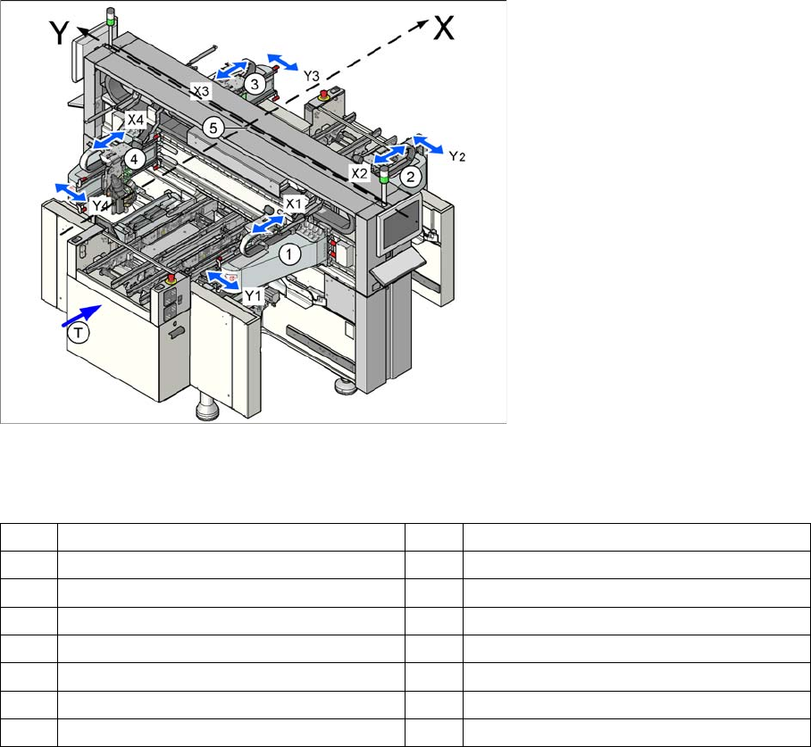
Position of the gantries in the X4I machine
Legend
Mechanic al Structure of X and Y A xes
6.1.1 Mechanical Structure of X and Y Axes
Please Note: X and Y Axes have the same basic mechanical parts.
X X axis – positive direction of travel Y Y axis – positive direction of travel
1 Gantry 1 in placement area 1 3 Gantry 3 in placement area 2
X1 X axis, gantry 1 X3 X axis, gantry 3
Y3 Y axis, gantry 1 G3 Y axis, gantry 3
2 Gantry 2 in placement area 2 4 Gantry 4 in placement area 1
X2 X axis, gantry 2 X4 X axis, gantry 4
Y2 Y axis, gantry 2 Y4 Y axis, gantry 4
T Transport direction 5 Coordinate origin