00194614-08 Trainingsdoku. SG X-Serie_X4i SW70x (AL2)_EN.pdf - 第188页
Gantry Reference Run at X and Y Axis (A364) Settings Student Guide SIPLACE X-Serie and X4I SW70x (AL2) 188 ▪ 2 motor phases are switched to the powe r supply of the servo a mplifier. ▪ The 3-pha se AC mot or moves to the…
Gantry
Gantry Reference Run (with A364) Reference Run Sequence at X and Y Axis (A364)
187 Student Guide SIPLACE X-Serie and X4I SW70x (AL2)
For X and Y axis position recognition we use incremental metal scales. These are positioned above the
secondary part for the X axis and below the secondary part of the Y axis. An incremental encoder reads
the increments, which are then sent to the axis controller boards, for determination of the axis positions
and for motor control.
Each X and Y axis has a rubber bumper as hardware stop at its ends.
Gantry Reference Run (with A364)
6.2 Gantry Reference Run (with A364)
Reference Run Sequence at X and Y Axis (A364)
6.2.1 Reference Run Sequence at X and Y Axis (A364)
Searchin g for the X and Y Commut ation Pos ition (A364)
6.2.2 Searching for the X and Y Commutation Position (A364)
A commutation position search for the 3 phases AC-drives on the gantry starts right after the head axes
reference run is succesfully finished.
1. Commutation position search during initial reference run:
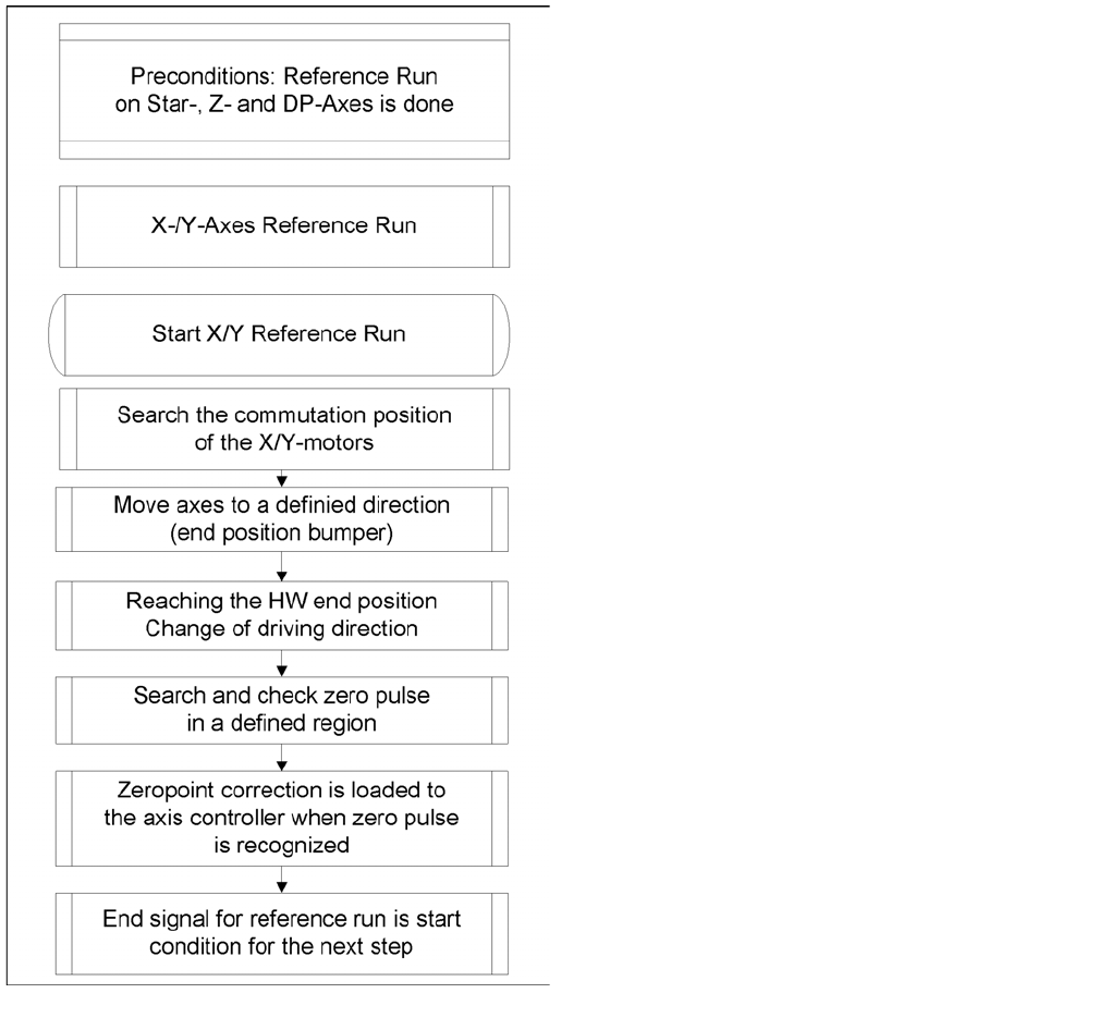
Preconditions and function:
▪ Axis reference run must be successfully completed at the relevant placement heads.
Reference run sequence
After the commutation search, the motor is in an
undefined position for the control system. When
referencing with bumper recognition (hardware end
stops), the axis moves successively against the
bumpers. For this purpose, fixed target values are set by
the axis controller, which are increasingly nearer to the
mechanical end stop.
After a certain time, this approach function reaches a
state in which the set target position is no longer reached
(actual position ≠ target position, the axis is at the
hardware end stop (bumper)).
After a certain time (approx. 10 ms) and after reaching a
certain motor current, the direction of travel is reversed
and the axis searches for the zero pulse within a specified
range. This zero pulse must be found within a predefined
travel range. If the zero pulse has been found in this area,
further zero pulses will be searched for in an area of
approx. 2.5 mm
After reaching and checking the zero pulse, the axis is in
a defined position.
The reference run for the main axes is started
simultaneously at all 4 gantries.
Gantry
Reference Run at X and Y Axis (A364) Settings
Student Guide SIPLACE X-Serie and X4I SW70x (AL2) 188
▪ 2 motor phases are switched to the power supply of the servo amplifier.
▪ The 3-phase AC motor moves to the next suitable magnetic position.
▪ 2 other motor phases are switched to the servo power supply and the axis moves further.
▪ These switching steps are repeated multiple times.
The axis reference run is continued with a reference position search for the position measuring system.
Referen ce Run at X and Y Axis (A364)
6.2.3 Reference Run at X and Y Axis (A364)
Zero pulse
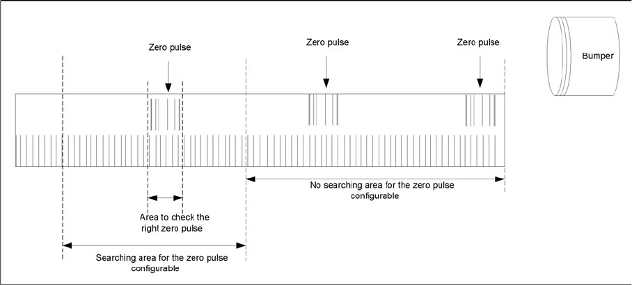
Description of zero pulse search:
▪ Requirements:
– The commutation point search has been completed.
– The motor is in position control.
1. After the hardware end stop has been reached and the axis has moved in the opposite direction, the
search for a zero pulse is prohibited within a certain distance of the bumper (approx. 25 mm).
2. After moving out of this prohibited area, the search begins. If the zero pulse is found in this area,
further pulses will be searched for in an area of approx. 2.5 mm If only one zero pulse is found, an
end position message is issued and the reference run is completed.
In the event of a fault, multiple zero pulses or no zero pulses may occur in the defined area. In this
case, the axis will stop and an error message with be issued.
3. The axes are now in a defined position. After finding and checking the zero pulse, the zero point
correction is loaded.
4. The reference run for the main axes has now been completed. The vacuum and height reference
runs will begin.
Settings
6.3 Settings
Travel Ranges and Speed Monitoring
6.3.1 Travel Ranges and Speed Monitoring
The travel range of the X and Y axes will be determined during machine calibration.
This means that, during travel range calibration, the axis concerned moves as far as possible towards
the minimum or maximum position, until the set target value is no longer reached by the axis card. It is
then assumed that the hardware limit switch (bumper) has been reached. In a time window of approx.
10 ms, the greatest actual value achieved is taken to calculate the travel range.
To guarantee an appropriate safety gap before the hardware end switch is touched, a certain distance
is deducted from the set travel range. This enables the axis to brake in time, even when errors occur.
Gantry
Settings Travel Ranges and Speed Monitoring
189 Student Guide SIPLACE X-Serie and X4I SW70x (AL2)
The X axis moves to the left and right bumper and measures their positions with a safety distance of 2.0
mm. The SW also deducts a value of 0.5 mm from the maximum or minimum travel range.
The Y axis moves to its minimum position (gantry 1/2) or to its maximum position (gantry 3/4).
The position opposite is then calculated.
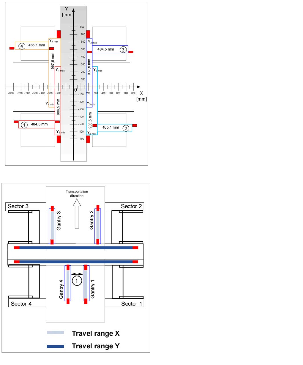
Travel ranges for X and Y axes (X4I)
Legend
▪ 1 - 4 = gantry 1 to 4
The end of the X axis travel range is + or - 0.5 mm before
the software limit switch, which is 1.5 mm before the
bumper. A safety distance of 2.0 mm to the bumper is
adequate, if the X axis moves into this area with
excessive speed.
The end of the Y axis travel range is + or - 2.0 mm before
the software limit switch. The Y axis travel range for a
particular placement area is monitored in one direction by
the software limit switch and a bumper. In the other
direction, there is a permanent exchange of
communication between the axes and their positions, via
the SPI Bus (see description of the anticrash function).
Travel ranges for X and Y axes
Legend
1. The minimum safety distance between the gantries,
during placement: minimum 4 mm.
Depending on the placement mode (i-placement or
alternating), the gantries will operate in one placement
area fully independently. This means that one gantry
does not need to know the position of the other one.