00194614-08 Trainingsdoku. SG X-Serie_X4i SW70x (AL2)_EN.pdf - 第199页
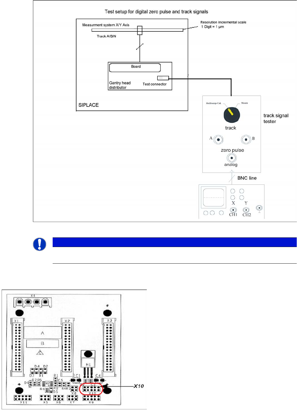
Gantry Track Signals and Zero Pulse Checkin g the Zero Pulse Signal 199 Student Guide SIPLACE X-Serie and X4I SW70x (AL2) Measurement procedure for checki ng the digital zero pulse si gnal and the digi tal track signals.…
Gantry
Checking the Zero Pulse Signal Track Signals and Zero Pulse
Student Guide SIPLACE X-Serie and X4I SW70x (AL2) 198
► Move the gantry manually over the zero pulse (see instructions or description of zero pulse search).
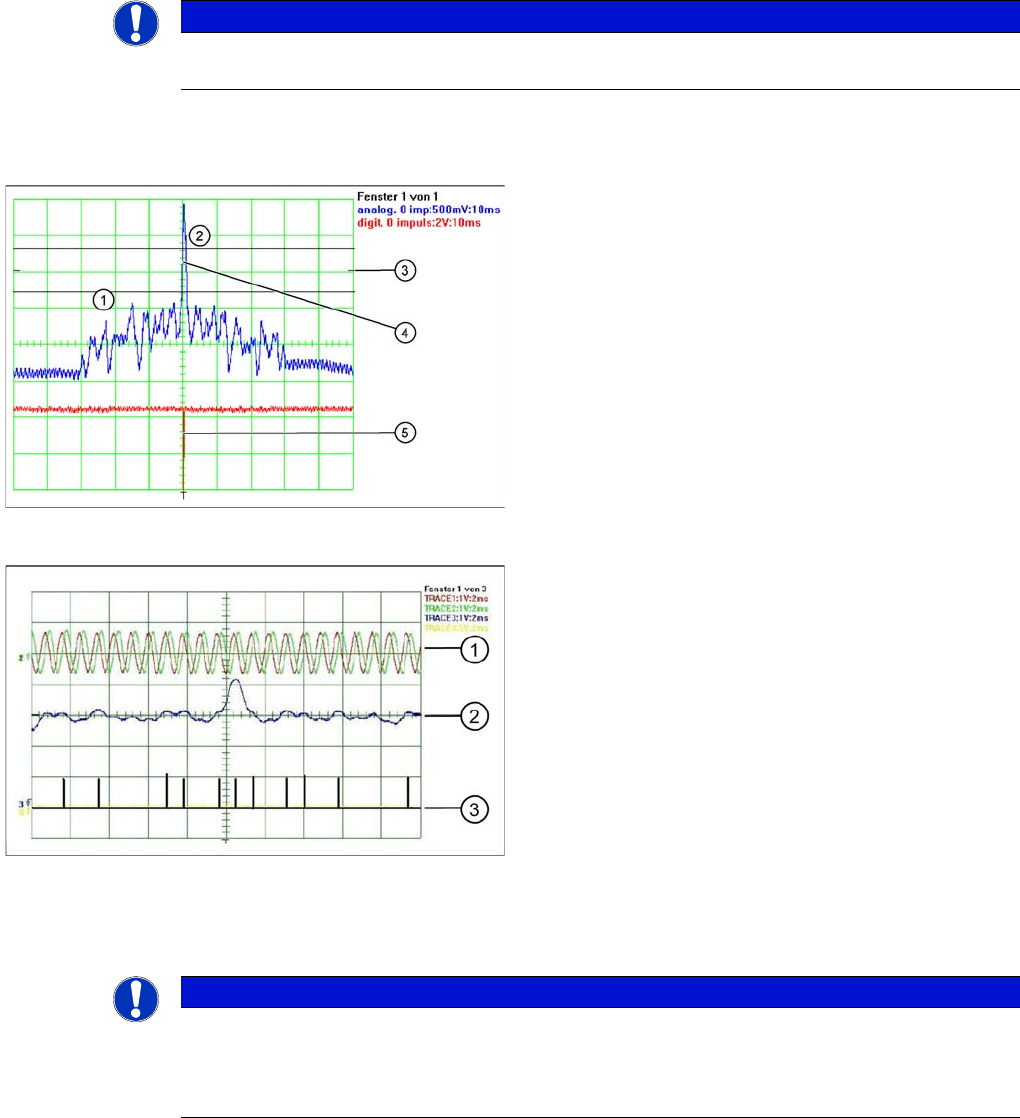
► The following picture should appear on the oscilloscope.
Measuring th e Digital Zer o Pulse Sign al
6.4.1.2 Measuring the Digital Zero Pulse Signal
NOTICE
When the gantry is positioned at the hardware stop, an area of 25mm begins, in which no zero
pulse search is permitted. Check the first zero pulse after this area, on the incremental scale.
Correctly adjusted read unit
Legend
1. There should be no interference pulse in the
tolerance space of - 0.3 V.
2. The analog zero pulse must overshoot the switching
threshold by more then 0.3V.
3. Initial position
4. Analog zero pulse
5. Digital zero pulse
Incorrectly adjusted read unit or contaminated zero pulse
Legend
1. Analog track signal A and B
2. Analog zero pulse
3. Digital zero pulse
NOTICE
You can also use the BNC socket on the axis test box to check the zero pulse signal (inverted
display of zero pulse signal). The digital signals can be checked (for error location) at
connectors X10 and X24 of the gantry and at the head interface (calculate extra time for Y axes,
dismantling the covers).
Gantry
Track Signals and Zero Pulse Checking the Zero Pulse Signal
199 Student Guide SIPLACE X-Serie and X4I SW70x (AL2)
Measurement procedure for checking the digital zero pulse signal and the digital track signals.
X10 on Y Axis Gantry Interfa ce
X10 on Y Axis Gantry Interface
NOTICE
The procedure for measuring the digital zero pulse is identical to that for measuring the analog
zero pulse.
Connector assignment X10:
1. Pin 1 Ground
2. Pin 2 Track A
3. Pin 3 Track A\
(A\ means inverted A)
4. Pin 4 Ground
5. Pin 5 Track B
6. Pin 6 Track B\
7. Pin 7 +5V
8. Pin 8 Track N
9. Pin 9 Track N\
10. Pin 10 Key
Gantry
Checking the Track Signals Track Signals and Zero Pulse
Student Guide SIPLACE X-Serie and X4I SW70x (AL2) 200
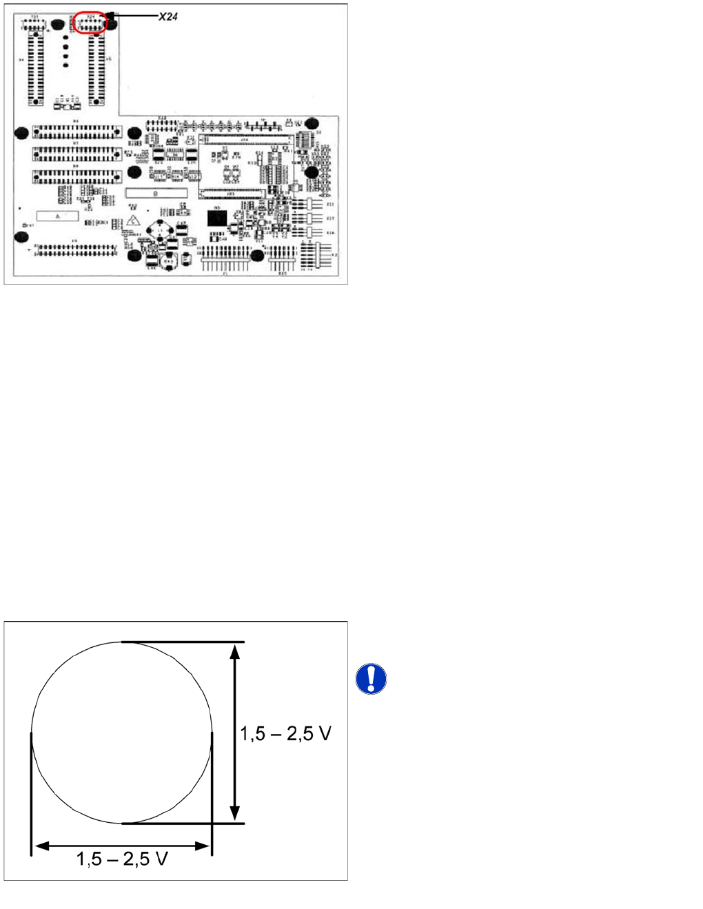
X24 on X Axis Head Interface
X24 on X Axis Head Interface
Checking the Track Signals
6.4.2 Checking the Track Signals
Analog Track Signals
6.4.2.1 Analog Track Signals
To check the track signals, connect the track signal tester and the oscilloscope. (see "6.4.1.1 Measuring
the Analog Zero Pulse Signal" [ ➙ 197])
► Switch the machine on.
► Switch the track signal tester to Calibrate oscilloscope.
► Switch the oscilloscope to DC, Refr., Non Store, Auto (20 ms).
► Voltages V/Division decrease up to 0.5 V/Div.
► Switch the oscilloscope to X/Y --> Illuminated point will appear!
► Move the point into the middle of the display.
► Measurement system to position Sinus amplifier output.
► Manually move the selected axis back and forth.
Connector assignment X24:
1. Pin 1 Ground
2. Pin 2 Track A
3. Pin 3 Track A\
4. Pin 4 Ground
5. Pin 5 Track B
6. Pin 6 Track B\
7. Pin 7 +5V
8. Pin 8 Track N
9. Pin 9 Track N\
10. Pin 10 Key
Analog track signals A and B in X/Y oscilloscope mode
► The adjacent picture should appear on the
oscilloscope.
NOTICE! A new version of the incremental
encoder (one field lens) can recognize signals from 1.8 to
3.6 Vss.