00194614-08 Trainingsdoku. SG X-Serie_X4i SW70x (AL2)_EN.pdf - 第201页
Gantry Track Signals and Zero Pulse Checking the Track Signals 201 Student Guide SIPLACE X-Serie and X4I SW70x (AL2) Digital T rack Signals 6.4.2.2 Digital Track Signals To check the digital track signals, conn ect the t…
Gantry
Checking the Track Signals Track Signals and Zero Pulse
Student Guide SIPLACE X-Serie and X4I SW70x (AL2) 200
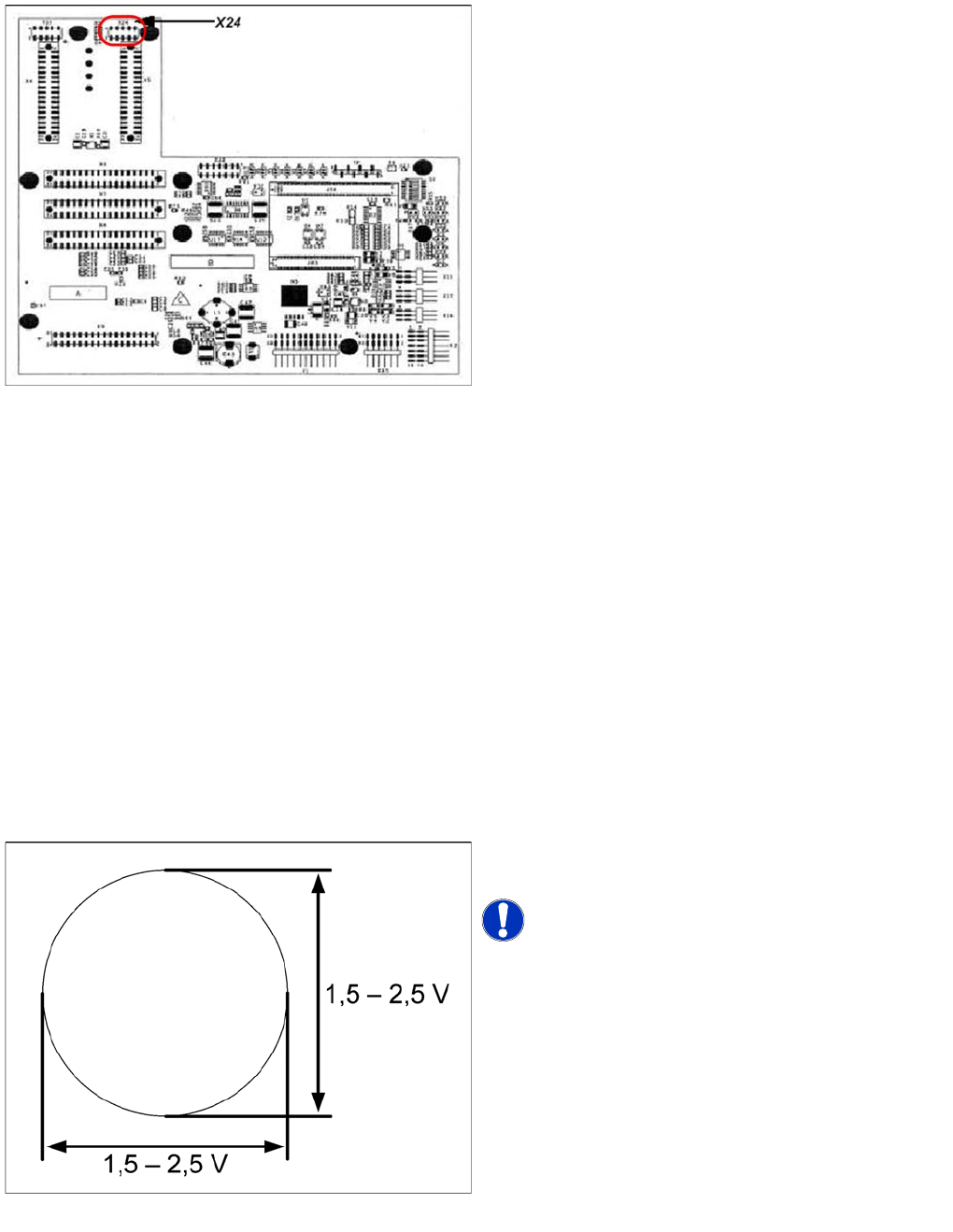
X24 on X Axis Head Interface
X24 on X Axis Head Interface
Checking the Track Signals
6.4.2 Checking the Track Signals
Analog Track Signals
6.4.2.1 Analog Track Signals
To check the track signals, connect the track signal tester and the oscilloscope. (see "6.4.1.1 Measuring
the Analog Zero Pulse Signal" [ ➙ 197])
► Switch the machine on.
► Switch the track signal tester to Calibrate oscilloscope.
► Switch the oscilloscope to DC, Refr., Non Store, Auto (20 ms).
► Voltages V/Division decrease up to 0.5 V/Div.
► Switch the oscilloscope to X/Y --> Illuminated point will appear!
► Move the point into the middle of the display.
► Measurement system to position Sinus amplifier output.
► Manually move the selected axis back and forth.
Connector assignment X24:
1. Pin 1 Ground
2. Pin 2 Track A
3. Pin 3 Track A\
4. Pin 4 Ground
5. Pin 5 Track B
6. Pin 6 Track B\
7. Pin 7 +5V
8. Pin 8 Track N
9. Pin 9 Track N\
10. Pin 10 Key
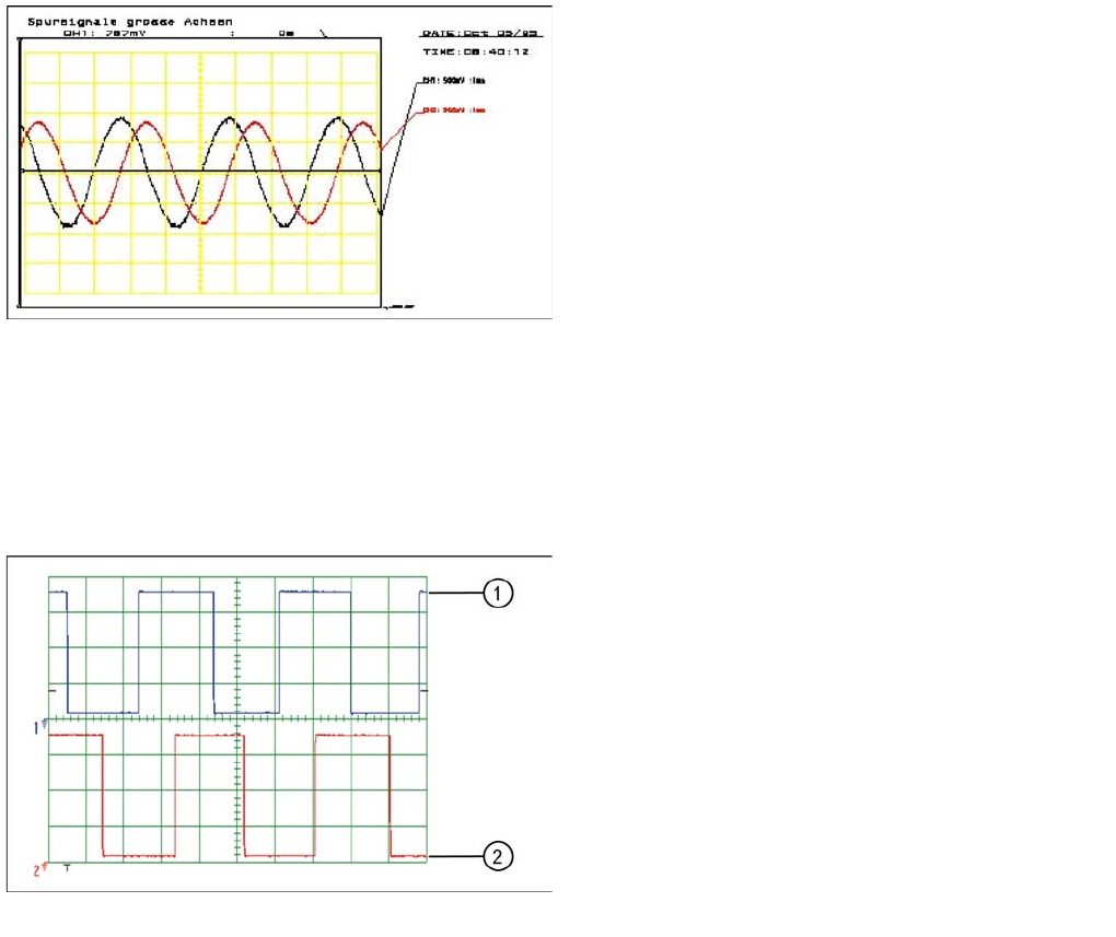
Analog track signals A and B in X/Y oscilloscope mode
► The adjacent picture should appear on the
oscilloscope.
NOTICE! A new version of the incremental
encoder (one field lens) can recognize signals from 1.8 to
3.6 Vss.
Gantry
Track Signals and Zero Pulse Checking the Track Signals
201 Student Guide SIPLACE X-Serie and X4I SW70x (AL2)
Digital T rack Signals
6.4.2.2 Digital Track Signals
To check the digital track signals, connect the track signal tester and the oscilloscope. (see "6.4.1.2
Measuring the Digital Zero Pulse Signal" [ ➙ 198])
The measurement sequence is identical to that described in "6.4.2.1 Analog Track Signals" [ ➙ 200].
Analog track signals 90° phase shift
► Switch the oscilloscope to normal operation.
► The adjacent picture should appear on the
oscilloscope.
Digital track signals 90° phase shift
Legend
1. Track A
2. Track B
Gantry
Axis Control Assemblies Axis Control
Student Guide SIPLACE X-Serie and X4I SW70x (AL2) 202
Axis Control
6.5 Axis Control
Axis Contro l Assemblies
6.5.1 Axis Control Assemblies
Checkin g the X Axis D ynamics
6.5.2 Checking the X Axis Dynamics
The inspection of dynamics occurs with the following signals:
▪ Deviation of position
▪ Uncommutated target current value
▪ End signal (adapter board, axis in target position)
▪ Actual position = target position signal (axis test box output end position signal)
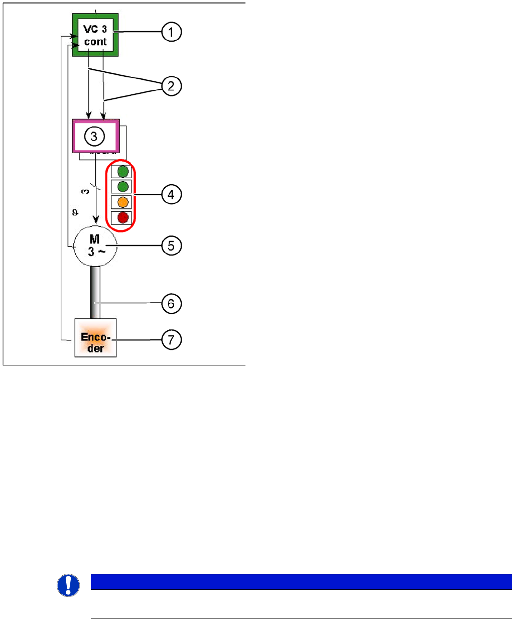
"Axis control" assemblies
The control loop for the X and Y axis consists of the
following parts:
▪ Axis card A363 with VC3 controller or A364
▪ Servo board (TDS)
▪ 3 phase AC linear motor
▪ Measurement system (incremental scale and
encoder (read unit))
To protect the linear motors from overtemperature, all
these motors have an internal temperature sensor.
Legend
1. Axis controller board A363 with VC3 controller (VC =
Velocity Commutation) or A 364
2. Control signals I
target "W"
and I
target "U"
3. Servo amplifier
4. LEDs on servo amplifier:
GREEN: power supply ON
GREEN: Servo enable, if the enable signal has been
received from the axis board.
ORANGE: Display R.M.S. current limiter shorter than
2.5 s.
RED: Error: overvoltage, overcurrent,
overtemperature longer than 2.5 sec.
5. 3-phase AC linear motor for X and Y axes with
integrated temperature sensor.
6. Between the motor and incremental encoder there is
a fixed mechanical connection.
7. Incremental encoder: transmits the exact position of
the axis. The track signals are the only feedback
signals for the axis control.
The servo board directly controls the linear motor, the
intermediate circuit voltage is 250 V.
NOTICE
Before checking the axis dynamics, make sure that the machine has reached its operating
temperature. Switch the machine on at least 30 minutes before you begin work.