00194614-08 Trainingsdoku. SG X-Serie_X4i SW70x (AL2)_EN.pdf - 第212页
C&P20A C&P20A Function Overview Student Guide SIPLACE X-Serie and X4I SW70x (AL2) 212 C&P20A Technical Data C&P20A Function 7.2.2 C&P20A Function C&P20A Pri nciple 7.2.2.1 C&P20A Principle ▪ L…
C&P20A
C&P20 And C&P20A Heads C&P20A Technical Data
211 Student Guide SIPLACE X-Serie and X4I SW70x (AL2)
C&P20A
7C&P20A
C&P20 An d C&P20A Heads
7.1 C&P20 And C&P20A Heads
Overview
7.2 Overview
C&P20A Technical Data
7.2.1 C&P20A Technical Data
NOTICE
The station software 70x generally supports the C&P20A heads. You recognize these by
means of a label attached to the front side of the placement head.
Machines with C&P20 heads which are upgraded from SW 60x to SW 70x will be recognized
by the station software. Thus they can still be used in the machine.
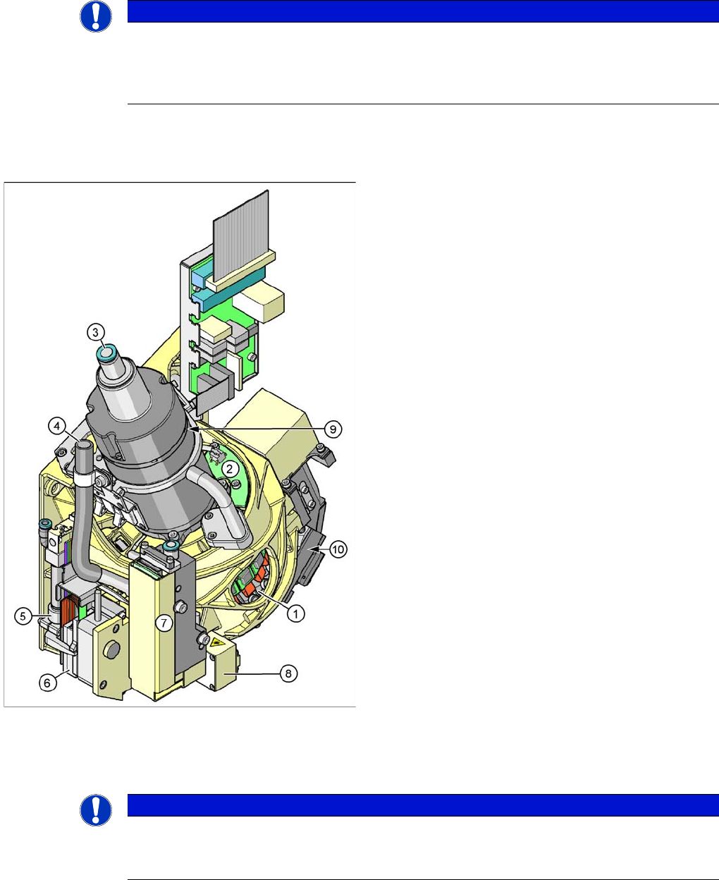
Collect&Place20 head overview
Legend
1. Star with 20 segments (DP drives)
2. Board for "holding circuit vacuum sensor"
3. Compressed air supply for holding, pickup and place
circuits
4. Cooling for X linear motor (discharged air from
pressure control valve)
5. Z axis return cylinder
6. Z linear motor with measuring system
7. Pressure control valve for pickup and place circuit
8. Component sensor
9. Star motor with incremental encoder
10. Component camera
NOTICE
Head Modularity
The axis dynamic settings at head replacement are adjusted automatically by axis parameter
changes during the reconfiguration.

C&P20A
C&P20A Function Overview
Student Guide SIPLACE X-Serie and X4I SW70x (AL2) 212
C&P20A Technical Data
C&P20A Function
7.2.2 C&P20A Function
C&P20A Principle
7.2.2.1 C&P20A Principle
▪ Like the C&P12, the C&P20A works according to the Collect&Place principle.
▪ While the Star revolves, the components can be rotated into the required placement position. After
optical measurement, the components are again rotated into the correct placement positions and
placed, while the star is revolving.
▪ This means that each segment is equipped with its own DP drive, to allow angle adjustment while
the star is revolving. Each DP drive has its own control board and vacuum generator.
▪ The communication with the 20 DP drives is carried out via the head CAN bus with the help of a
contactless E/D transformer. This makes continuous star rotation possible.
▪ In the pickup / placement circuit, the Z axis moves the complete DP drive unit upwards or
downwards.
▪ Compressed air is supplied to the 20 Venturi nozzles in the holding circuit via the hollow designed
shaft of the Star motor.
▪ A pressure control valve in the pickup/placement circuit is used to increase the vacuum during pickup
and apply air blast to eliminate the holding circuit vacuum and release the component, during
placement.
▪ The component sensor which is installed in the pickup/placement circuit by default is used to check
the presence of components on the nozzle, both before and after pickup/placement.
Advantages Compared with DLM Heads
7.2.2.2 Advantages Compared with DLM Heads
▪ The holding circuit has one venturi nozzle for each segment: No interference between the segments.
▪ No vacuum plunger: Digital pressure control valve: Faster switching times between vacuum and air
blast.
▪ The placement star is now positioned at an angle which leads to a compact space for arranging the
20 segments and integrating the component camera into the head.
▪ Lower inlet pressure: Low air consumption per segment.
▪ Autonomous rotation and positioning of each segment: Increases placement rate.
▪ No swiveling in and out of DP station onto the segment: Greater accuracy and robustness.
▪ Component sensor in the pickup/placement position: Greater placement reliability.
▪ Digital camera interface: Faster image evaluation
▪ Linear motor as Z drive: Reduction of moving mass. This increases placement rate.
Description C&P20A
Component size 01005 to 2220, Melfs, Bare Dies, Flip Chips, SOT, SOD, components up to max.
6x6mm
Component height 4.0 mm
Component weight max. 1g
Placement accuracy +/-55µm at 4 (sigma)
Angle accuracy +/-0.8° at 4 (sigma)
Placement force 2.0 N +/-0.5 N
3.5 N and 4.5 N +/-1 N
Nozzle types 1001, 1003-1007, 1011, 1032-1037, at which 1235 is for the calibration tool
Nozzle changer 6 magazines with 12 garages each which are freely configurable,
X4I: four magazines each at locations 2 and 4
C&P20A
Overview Parts Overview with Function Description
213 Student Guide SIPLACE X-Serie and X4I SW70x (AL2)
Parts Ov erview w ith Function Desc ription
7.2.3 Parts Overview with Function Description
Pressure Control Valve
7.2.3.1 Pressure Control Valve
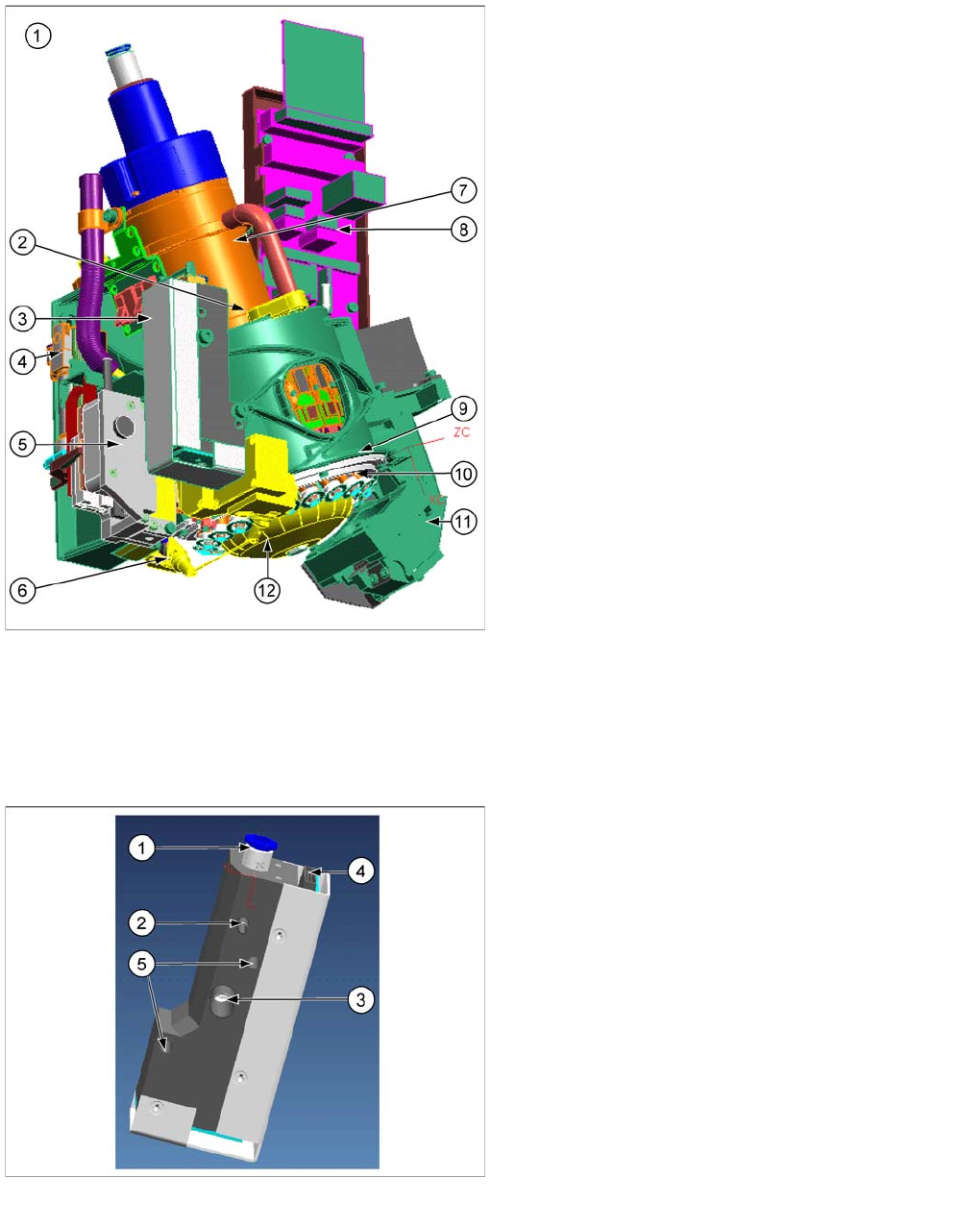
C&P20A function units
C&P20A parts
This section describes the main parts of the C&P20A
head and their technical function.
The description is ordered according to the sequence of
disassembly for servicing.
Legend
1. C&P20A assembly
2. E/D transformer
3. Vacuum generator for placement circuit
4. Pneumatic retract unit
5. Z drive
6. Component sensor
7. Star motor
8. Intermediate distributor board
9. Raceway
10. DP drive
11. Component camera
12. Silencer holding circuit
Pressure control valve (digital)
▪ The pressure control valve supplies the pickup/
placement circuit with vacuum during the pickup
process and switches over to air blast during
placement.
▪ The pressure control valve is fixed to the placement
head with two screws and can be replaced during
service work.
Legend
1. Compressed air connection
2. Vacuum/air blast for pickup/placement circuit
3. Discharged air for cooling the X-linear motor (SX4
and X series machines only).
4. Energy and data supply
5. Pressure control valve fixture