00194614-08 Trainingsdoku. SG X-Serie_X4i SW70x (AL2)_EN.pdf - 第214页
C&P20A Parts Overview with Function Description Overview Student Guide SIPLACE X-Serie and X4I SW70x (AL2) 214 Pressure Control Valve - Function Pressure Control Valve - Function Z Axis 7.2.3.2 Z Axis Legend A : Pist…
C&P20A
Overview Parts Overview with Function Description
213 Student Guide SIPLACE X-Serie and X4I SW70x (AL2)
Parts Ov erview w ith Function Desc ription
7.2.3 Parts Overview with Function Description
Pressure Control Valve
7.2.3.1 Pressure Control Valve
C&P20A function units
C&P20A parts
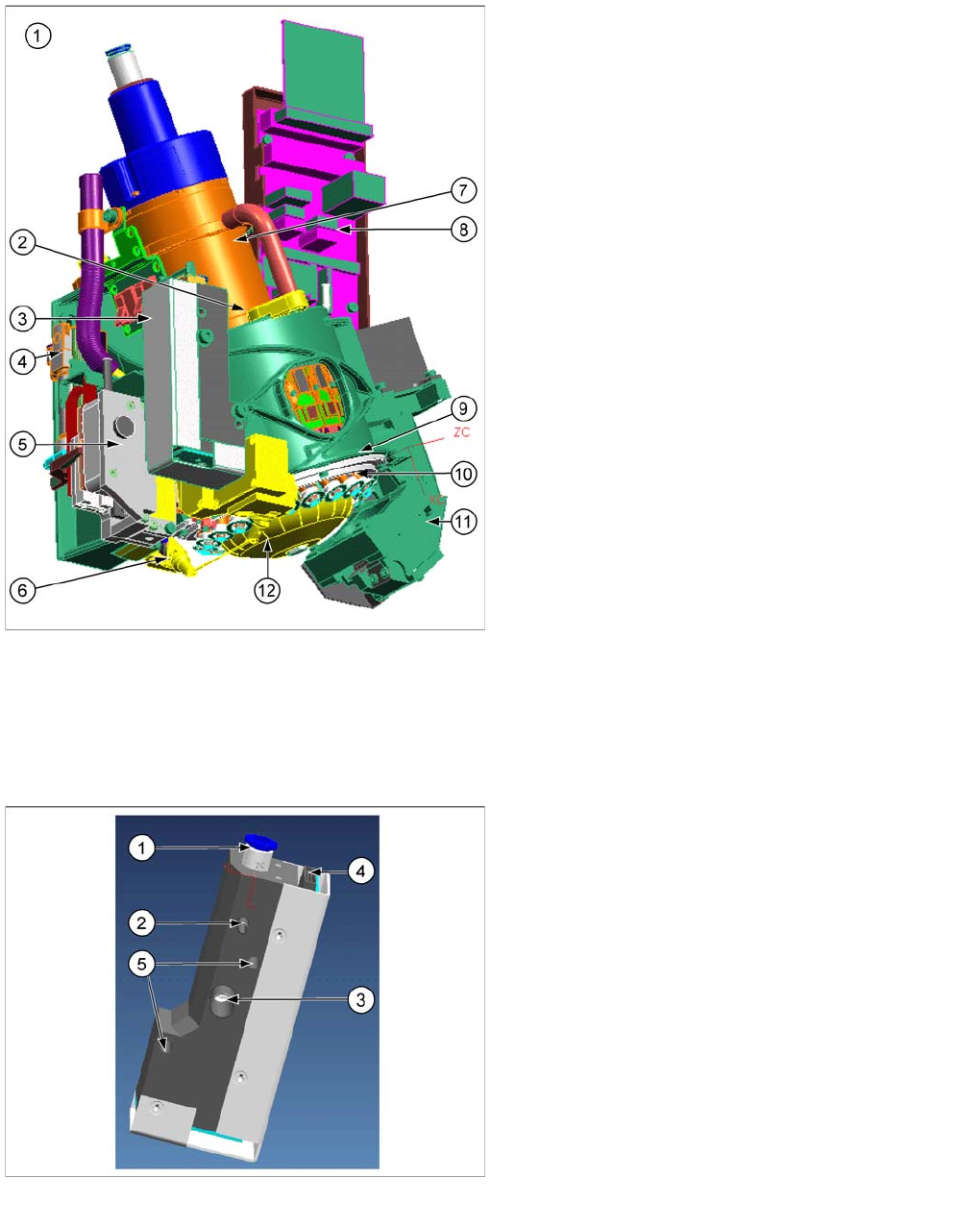
This section describes the main parts of the C&P20A
head and their technical function.
The description is ordered according to the sequence of
disassembly for servicing.
Legend
1. C&P20A assembly
2. E/D transformer
3. Vacuum generator for placement circuit
4. Pneumatic retract unit
5. Z drive
6. Component sensor
7. Star motor
8. Intermediate distributor board
9. Raceway
10. DP drive
11. Component camera
12. Silencer holding circuit
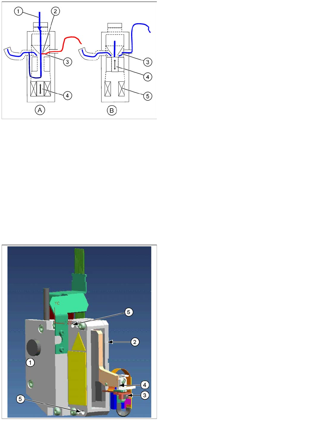
Pressure control valve (digital)
▪ The pressure control valve supplies the pickup/
placement circuit with vacuum during the pickup
process and switches over to air blast during
placement.
▪ The pressure control valve is fixed to the placement
head with two screws and can be replaced during
service work.
Legend
1. Compressed air connection
2. Vacuum/air blast for pickup/placement circuit
3. Discharged air for cooling the X-linear motor (SX4
and X series machines only).
4. Energy and data supply
5. Pressure control valve fixture
C&P20A
Parts Overview with Function Description Overview
Student Guide SIPLACE X-Serie and X4I SW70x (AL2) 214
Pressure Control Valve - Function
Pressure Control Valve - Function
Z Axis
7.2.3.2 Z Axis
Legend
A : Piston setting for max. vacuum during pickup
B : Piston setting for air blast during placement
1. Compressed air inlet
2. Venturi nozzle
3. Vacuum or air blast outlet, depending on piston
setting
4. Pistons
5. Motor
▪ After initialization, the piston is in a central position, in
which neither vacuum nor air blast is applied to the
nozzle.
▪ During pickup, the piston is always in the Open
position, so that maximum vacuum is generated and
is present at the nozzle. The switchover time
(pressure build up time) between max. vacuum of –
850 mbar to max. air blast of +200 mbar ≤ 12 ms.
▪ The function Early vacuum should always be
switched on for the CPx head. However, if this
function is switched off, the piston will be in the "open
position". The vacuum will only be switched on again
after the "light barrier down" signal has been issued .
-> 2 additional switching steps -> time loss.
Legend
1. Incremental measurement system, resolution 0.5 µm
2. Linear motor, primary part, moves up and down
between the secondary parts.
3. Light barrier Z-down emits the end position signal for
the Z axis.
4. Snap jaws: The ball bearing for the DP drive is
rotated via the star axis into the jaw, allowing the
segment to be moved upwards and downwards.
5. Z axis fixtures
The Z axis and retract unit are fixed to the head as a
complete unit, with two screws, and can be easily
replaced during service work.
C&P20A
Overview Parts Overview with Function Description
215 Student Guide SIPLACE X-Serie and X4I SW70x (AL2)
Z Drive Function
Z Drive Function
Retract Unit
7.2.3.3 Retract Unit
Retract unit functions
At zero current, the bearing friction of the Z axis is not sufficient to protect the axis from falling down. A
pneumatic retract system has been installed to protect the Z axis should the gantry be moved when the
machine is switched off. This retract unit keeps the Z axis in the safe, upper position during zero current.
Legend
1. Raceway
2. Segment
3. Ball bearings
4. Light barrier down
5. Snap jaws
▪ The jaws are installed on the primary part of the Z
motor, for mechanical docking of the segments.
▪ A Z down sensor is located in the placement position,
for recognition of the Z axis put down position. This
recognizes a relative movement between the nozzle
and DP segment. When the Z axis springs into place,
this sensor sends a signal to the axis controller board.
The "light barrier down" signal is directly linked to the
measurement signal of the Z axis incremental
encoder.
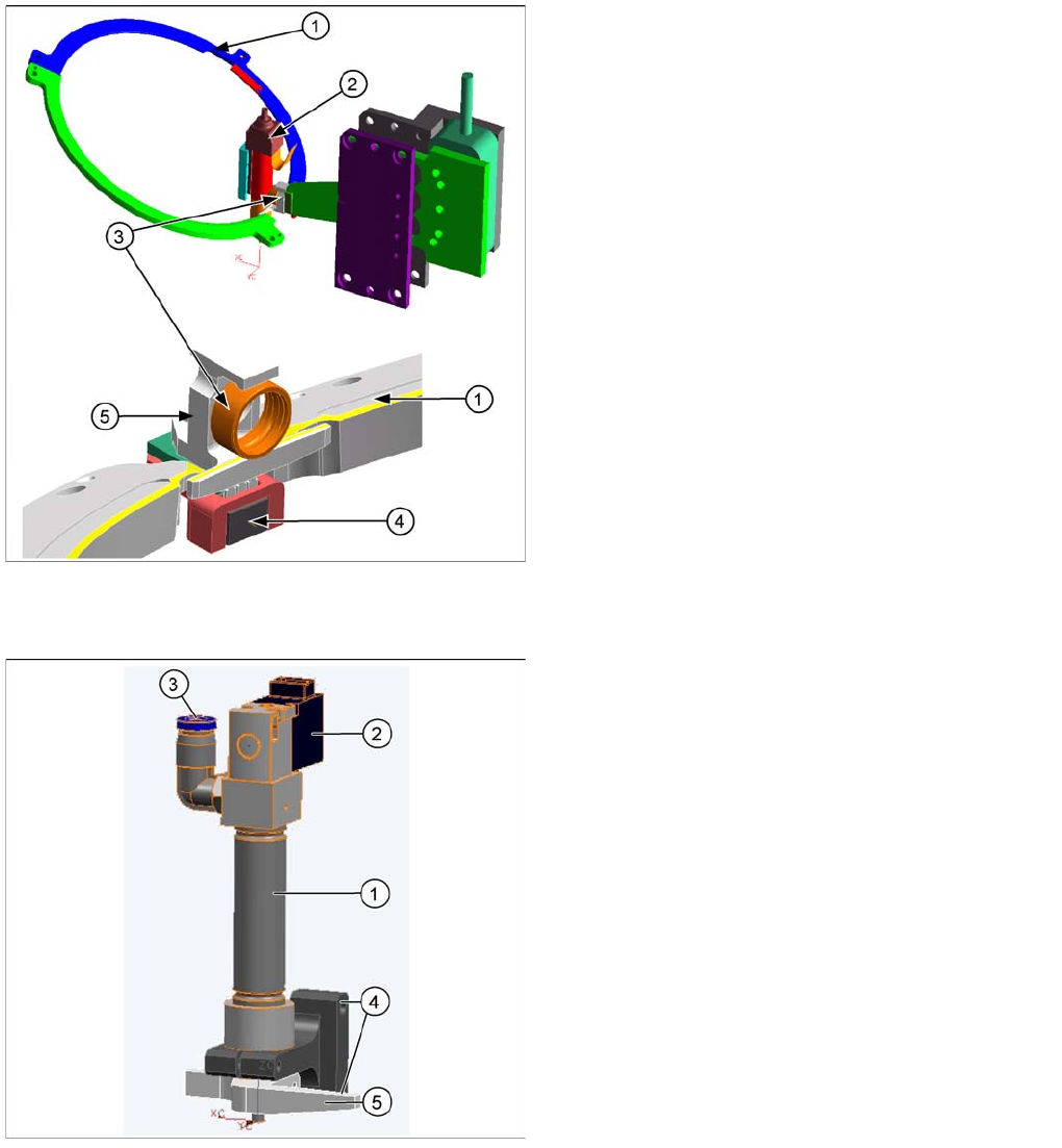
Legend
1. Pneumatic cylinder
2. Solenoid valve
3. Compressed air connection
4. Retract unit fixtures
5. Z axis driver
The retract unit is installed on the Z axis and is
responsible for protecting the Z axis from damage, by
moving it into a safe area in the case of unexpected
events e.g. power cuts or machine shutdown.
The retract unit is fixed with two screws and can be easily
replaced during service work.