00194614-08 Trainingsdoku. SG X-Serie_X4i SW70x (AL2)_EN.pdf - 第217页
C&P20A Overview Parts Overview with Function Description 217 Student Guide SIPLACE X-Serie and X4I SW70x (AL2) Component S ensor Funct ions Component Sensor Functions Pickup Process: When the Z axis moves do wnwards,…
C&P20A
Parts Overview with Function Description Overview
Student Guide SIPLACE X-Serie and X4I SW70x (AL2) 216
Component Sensor
7.2.3.4 Component Sensor
The component sensor is a standard feature on the C&P20A head and no longer an option as in the DLM
heads. Also, the function and position of the component sensor is different to that for the DLM heads.
The component sensor is in the pickup/place position and the Z axis moves during the upwards and
downwards movement of the laser beam. If the laser beam is interrupted or when it is released again,
the exact Z axis position is read out and the corresponding evaluation started.
(Before pick up: no component on the nozzle, after Pick up: component on the nozzle;
placement: component still on the nozzle, after placement: no component on the nozzle)
NOTICE
The Z axis control system is designed to ensure that, should the machine power supply fail (or
be switched off), there is always enough power temporarily stored by the Z motor servo unit and
axis controller board to move the Z axis to the upper position.
Power failure is recognized by the issuance of a "Power fail" signal. This "Power fail" signal
enables the relevant function (upwards movement and activation of the retract unit) on the axis
controller board.
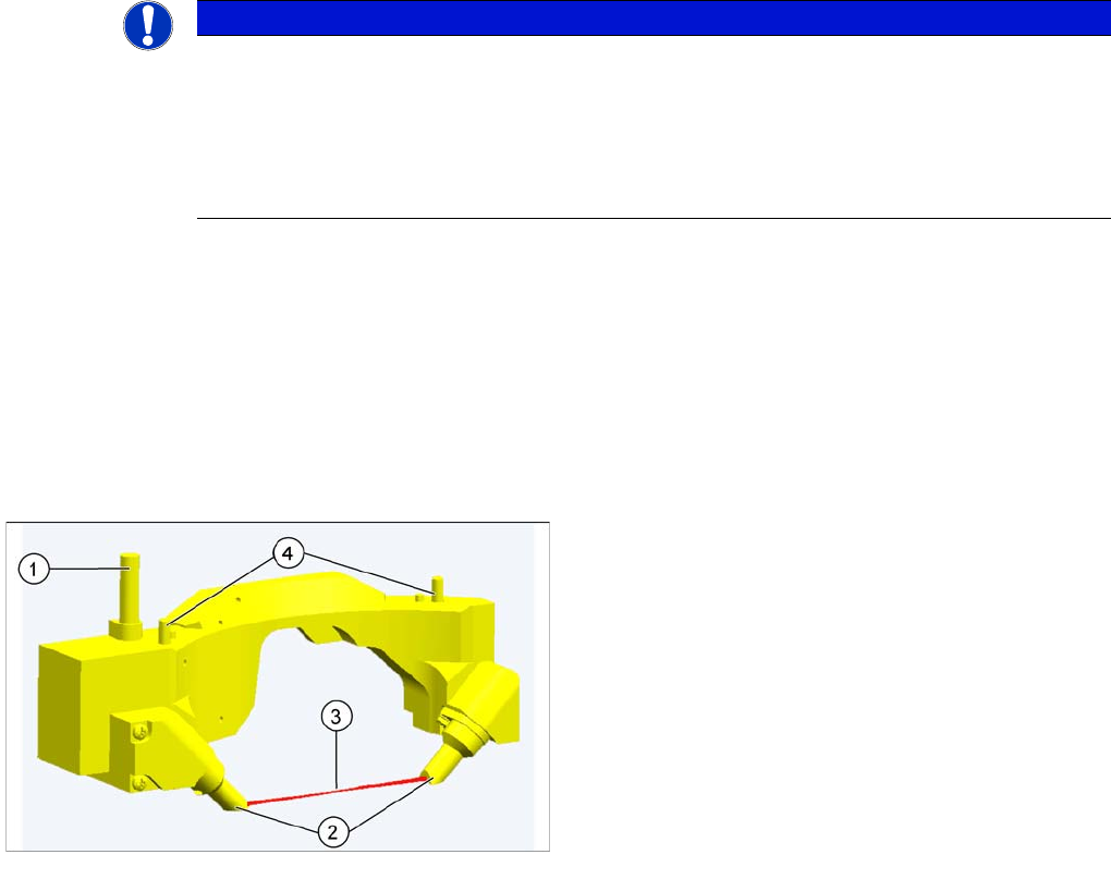
Component sensor
▪ The component sensor is installed in the pickup-
placement position on the C&P20A head, by default.
▪ The sensor is fixed to the head with two screws and
can be replaced as a complete unit during service
work.
Legend
1. Power/data supply cable
2. Transmitter and receiver unit
3. Laser beam
4. Fixture to housing
C&P20A
Overview Parts Overview with Function Description
217 Student Guide SIPLACE X-Serie and X4I SW70x (AL2)
Component Sensor Functions
Component Sensor Functions
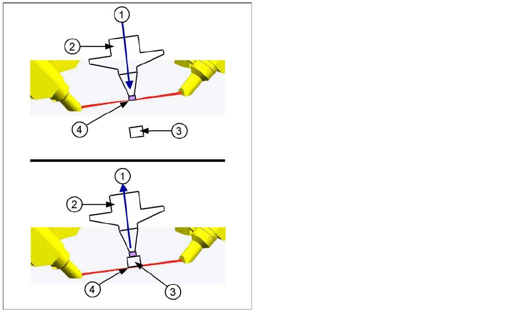
Pickup Process:
When the Z axis moves downwards, the nozzle interrupts the laser beam. At this exact moment, this Z
axis position is read out and compared to the reference value, from the height reference run, or from this
segment after placement. This determines whether there is still a component on the nozzle or not. If the
Z axis position indicates that there is a component on the nozzle, the Z axis will be immediately stopped.
An error message will appear or the component will be rejected and added to the repair cycle as not
placed.
When the Z axis moves upwards again, the laser beam is released and the Z position read out. Based
on the Z position during downwards movement, the system can now determine the presence and height
of a component.
Placement Process:
During the placement process, the system checks whether the component is at the nozzle (Z downwards
movement) or whether placement has been performed on the component (Z upwards movement). As a
precaution, these Z positions are compared to those from the pickup procedure.
This ensures maximum pickup and placement reliability.
Legend
1. Downwards (top diagram) or upwards (bottom
diagram) movement
2. Nozzle
3. Component
4. Reading out the Z position, if the laser beam is
interrupted (top diagram) or has been released again
(bottom diagram).
The component sensor signal is directly linked to the axis
controller (measurement system) of the Z axis. This
enables you to read out the Z position during upwards
and downwards movement.
C&P20A
Parts Overview with Function Description Overview
Student Guide SIPLACE X-Serie and X4I SW70x (AL2) 218
Star As sembly
7.2.3.5 Star Assembly
Star Frame
Star Frame
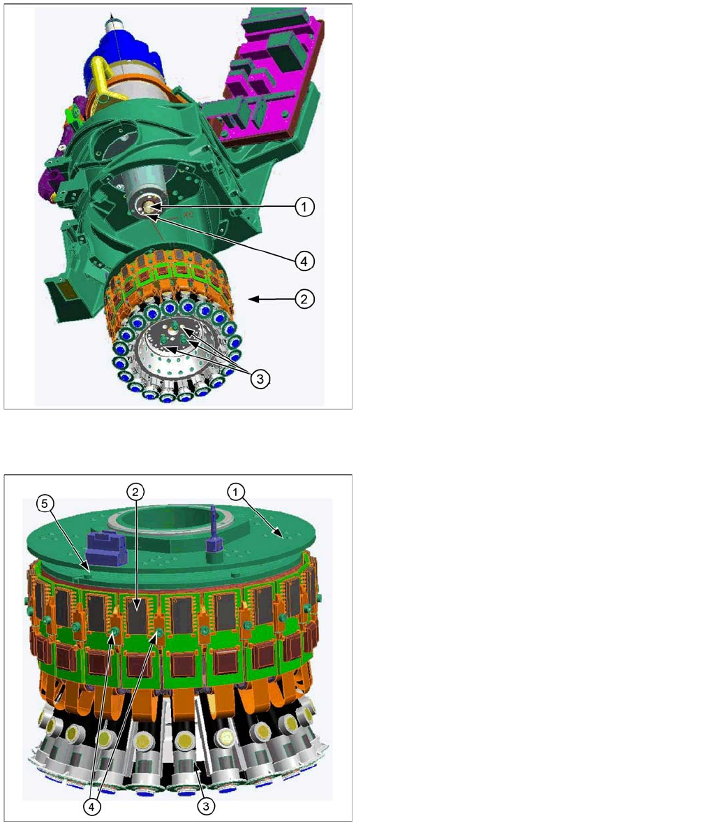
The mechanical E/D transformer (1) consists of a stationary and a rotating part. The 6 sliding contacts
transmit direct voltage (24V/4A), ground and the CAN bus signals (CAN high, CAN low).
Legend
1. Motor shaft
2. Star assembly
3. Screws (3) mounting the star unit to the motor shaft
4. Smoothed distributor disc
The star consists of the star frame, on which all 20 DP
drives are located, the motherboard and the E/D
transformer.
This complete unit is fixed to the motor shaft with three
screws and can be removed for service work after the
raceway has been dismounted.
▪ Above the star you will find the E/D transformer (1) for
supplying energy and data to the DP drives.
▪ The motherboard is located behind the control boards
(2) of the DP drives (3) and is responsible for
controlling and positioning the DP drives.
▪ The control board is plugged into the motherboard.
and is fixed via the two brackets (4).
▪ Two screws fix the complete DP drive unit from
inside, to the star frame.
▪ An index screw (5) ensures that the ED transformer
is correctly positioned during assembly.