00194614-08 Trainingsdoku. SG X-Serie_X4i SW70x (AL2)_EN.pdf - 第231页
C&P20A Reference Run for C&P20A Head Height Reference Run 231 Student Guide SIPLACE X-Serie and X4I SW70x (AL2) Measuring the nozzle height Legend ▪ The gantr y moves the placeme nt head to th e fixed co nveyor s…
C&P20A
Cleaning Cycle - Procedure Reference Run for C&P20A Head
Student Guide SIPLACE X-Serie and X4I SW70x (AL2) 230
▪ The DP axes can also be referenced independently of the star and Z axes.
▪ By determination of the largest amplitude of the Hall sensor becomes the 0° position of the nozzle in
the factory (mechanically adjusted) and can't be changed.
The C&P head reference run has been successfully completed!
The gantry reference run follows – see Chapter Gantry
Cleaning Cycle - Procedur e
7.3.5 Cleaning Cycle - Procedure
Height R eference Run
7.3.6 Height Reference Run
With this function we check the correct fitting of the nozzle on the sleeve and that the correct nozzle type
like the programmed one are set to the sleeves. The nozzle length is taken to calculate the pick up and
placement height for the subsequent placements.
Vacuum check procedure
▪ The gantry axes move the C&P head to the reject
position so that the nozzles can be cleaned before
the measuring cycle.
▪ The Star axes move in an anticlockwise direction and
all cleaning functions are performed at the same time,
within one head cycle.
1. The DP drives rotate each segment into the 0°
position.
2. The digital pressure control valve now activates the
air blast for the reject position. The components still
on the nozzle will be rejected.
NOTICE
In SIPLACE SX and X machines, components are rejected vertically downward.
C&P20A
Reference Run for C&P20A Head Height Reference Run
231 Student Guide SIPLACE X-Serie and X4I SW70x (AL2)
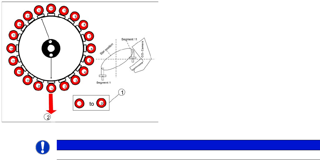
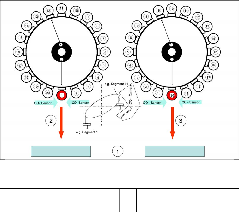
Measuring the nozzle height
Legend
▪ The gantry moves the placement head to the fixed conveyor side at height measurement position.
▪ The star turns the segment for measuring into the pickup/placement position
▪ The value "Vacuum open" is measured for each segment.
The Z axis is positioned downwards:
▪ When the component sensor beam is interrupted, the Z position of the axis is determined for the
component sensor.
▪ When the Z axis touches the conveyor side, the mechanical nozzle length is determined by the Z
position value and the closed vacuum value is measured.
The Z axis is positioned upwards:
▪ When the component sensor beam is no longer interrupted, the Z position of the axis will be
measured again for the component sensor.
1 Top edge of the fixed conveyor side 3 Last step with segment 20 to measure the
nozzle length.
2 First step with segment 1 to measure the
nozzle length.
C&P20A
Height Reference Run Reference Run for C&P20A Head
Student Guide SIPLACE X-Serie and X4I SW70x (AL2) 232
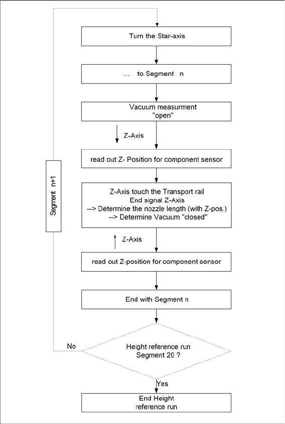
Sequence of Height Reference Run
7.3.6.1 Sequence of Height Reference Run
Height reference run flow chart