00194614-08 Trainingsdoku. SG X-Serie_X4i SW70x (AL2)_EN.pdf - 第254页
C&P20A Board Descriptions for C&P20A Settings Student Guide SIPLACE X-Serie and X4I SW70x (AL2) 254 Intermediate Distributor - C&P20 Intermediate Distributor - C&P20 Intermediate distributor - position of…
C&P20A
Settings Board Descriptions for C&P20A
253 Student Guide SIPLACE X-Serie and X4I SW70x (AL2)
Base Ada pter for CPx head s (for SX 1/2)
7.5.1.4 Base Adapter for CPx heads (for SX1/2)
The Base Adapter PCB (Part Number 03055516-xx) has the same purpose as the Head Adapter that is
used on the X series machines. It is used on the SX machines with both the CP20 and CPP heads.
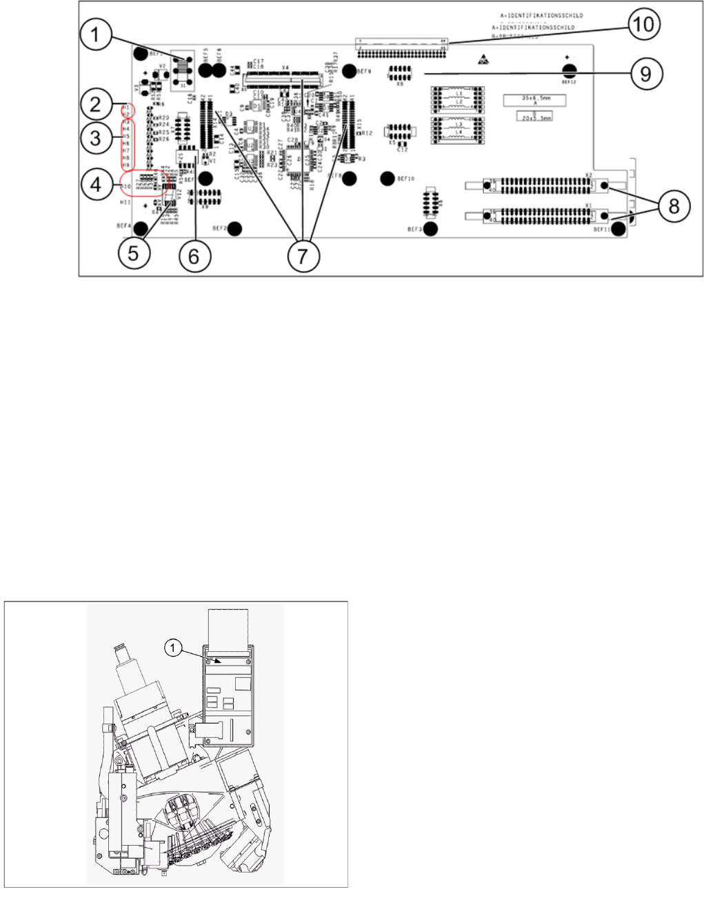
1. Switch S1
2. H1 – H2 (Head)
3. H3 – H9 (Power Failure)
4. H10 – H11 (HCU)
5. 7 segment display
6. DIP switch block S2.
7. X4 - X14 – X15 connectors for the HCU.
8. X1 – X2 ribbon cables to the head.
9. X8 Service connector for checking voltages
10. X3 connector to the head interface C700.
Arrangem ent of Intermedia te Distri butors for C&P20A
7.5.1.5 Arrangement of Intermediate Distributors for C&P20A
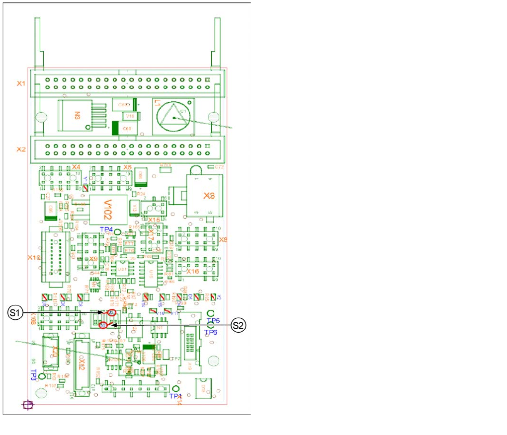
Intermediate distributors for C&P20A
Legend
1. Intermediate distributor board
C&P20A
Board Descriptions for C&P20A Settings
Student Guide SIPLACE X-Serie and X4I SW70x (AL2) 254
Intermediate Distributor - C&P20
Intermediate Distributor - C&P20
Intermediate distributor - position of the sockets
Legend
The following supply voltages and signals are routed by
the intermediate distributor to the individual placement
head modules or to the head board:
▪ Connector X1, 40 pole: connected with connector X1
on the head adapter board
▪ Connector X2, 40 pole: connected with connector X2
on the head adapter board
▪ Connector X3: connection for the star motor
▪ Connector X4: connection for the star incremental
encoder
▪ Connector X6: connection for the Z axis incremental
encoder
▪ Connector X8: connection for the Z motor
▪ Connector X9: connection for the component sensor
▪ Connector X12: connection for pressure control valve
▪ Connector X14: test connector X14_3: +5 V/X14_4:
+15 V/X14_5: -15 V/X14_7:24 V for DP motors
▪ Connector X15: connection for retract unit
▪ Connector X16: Internal CAN bus C&P20
C&P20A
Settings Board Descriptions for C&P20A
255 Student Guide SIPLACE X-Serie and X4I SW70x (AL2)
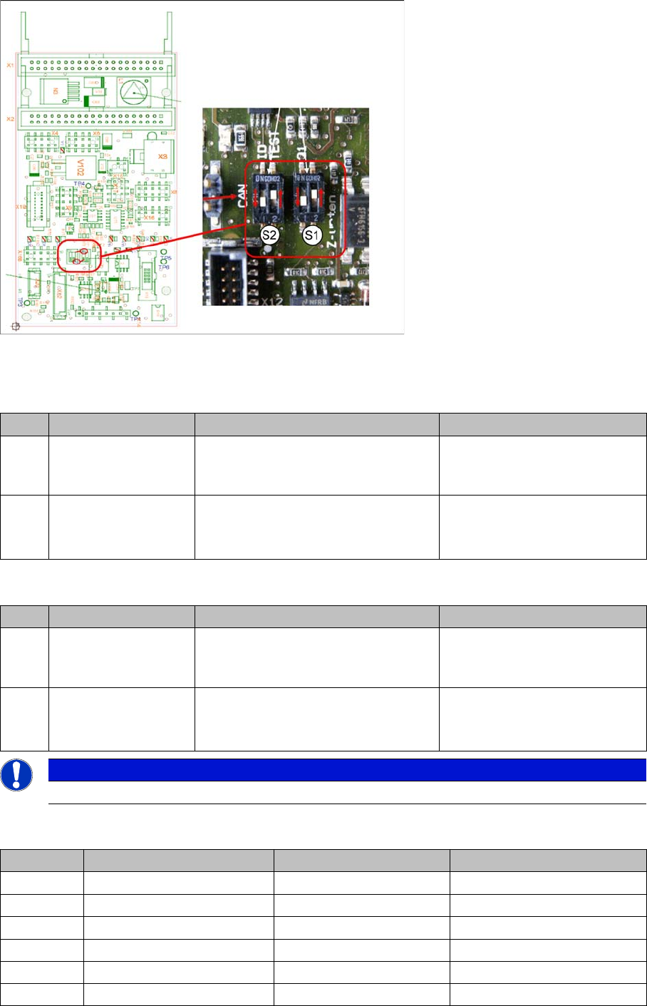
Switch setting S1, S2
Intermediate distributor - position of DIP switch
S1 (default setting: bold)
S2 (default setting: bold)
LEDs - meanings:
No. Function Switch setting = 0 (open) Switch setting = 1 (closed)
S1.1 Z down sensor:
switch on LED
LED is only switched on during
operation
LED always on (test mode e.g.
for detection of nozzle
suspension with oscillo.)
S1.2 Z-down sensor:
activating LED in
clocked mode
LED is activated in clocked mode
during
operation
LED is always switched on
during operation
No. Function Switch setting = 0 (open) Switch setting = 1 (closed)
S2.1 CAN test Normal operation: 1-wire head CAN
bus only with motherboard - ready for
operation
Test mode: operation without
motherboard possible
S2.2 CAN ID switchover -
pressure control valve
CAN ID active for pressure control
valve
0x6B0
CAN ID for pressure control
valve 0x6B8 (test mode)
NOTICE
The default switch setting is always printed in bold.
No. Function On Off
D3 +5 V Present Not present
D4 Z down Triggered Not triggered
D5 Z down reset Reset Not reset
D6 +15 V Present Not present
D7 +24 V_IN
D8 -15 V Present Not present