00194614-08 Trainingsdoku. SG X-Serie_X4i SW70x (AL2)_EN.pdf - 第256页
C&P20A Setting the Nozzle Changer for C&P20A Settings Student Guide SIPLACE X-Serie and X4I SW70x (AL2) 256 Test points: Test connector X14: Setting t he Nozzle Change r for C&P 20A 7.5.2 Setting the Nozzl e …
C&P20A
Settings Board Descriptions for C&P20A
255 Student Guide SIPLACE X-Serie and X4I SW70x (AL2)
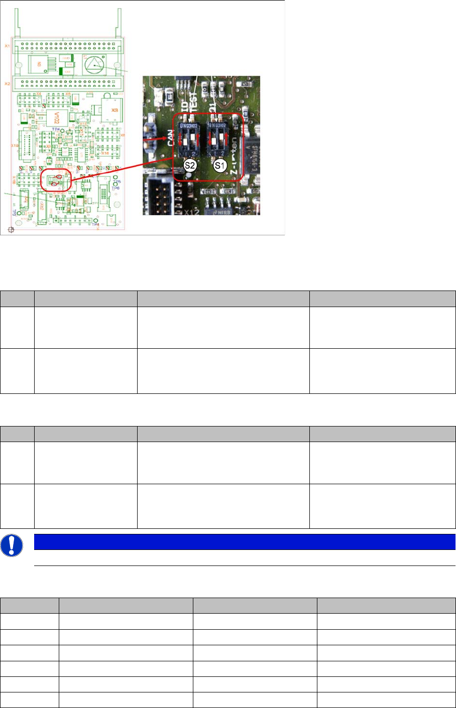
Switch setting S1, S2
Intermediate distributor - position of DIP switch
S1 (default setting: bold)
S2 (default setting: bold)
LEDs - meanings:
No. Function Switch setting = 0 (open) Switch setting = 1 (closed)
S1.1 Z down sensor:
switch on LED
LED is only switched on during
operation
LED always on (test mode e.g.
for detection of nozzle
suspension with oscillo.)
S1.2 Z-down sensor:
activating LED in
clocked mode
LED is activated in clocked mode
during
operation
LED is always switched on
during operation
No. Function Switch setting = 0 (open) Switch setting = 1 (closed)
S2.1 CAN test Normal operation: 1-wire head CAN
bus only with motherboard - ready for
operation
Test mode: operation without
motherboard possible
S2.2 CAN ID switchover -
pressure control valve
CAN ID active for pressure control
valve
0x6B0
CAN ID for pressure control
valve 0x6B8 (test mode)
NOTICE
The default switch setting is always printed in bold.
No. Function On Off
D3 +5 V Present Not present
D4 Z down Triggered Not triggered
D5 Z down reset Reset Not reset
D6 +15 V Present Not present
D7 +24 V_IN
D8 -15 V Present Not present
C&P20A
Setting the Nozzle Changer for C&P20A Settings
Student Guide SIPLACE X-Serie and X4I SW70x (AL2) 256
Test points:
Test connector X14:
Setting t he Nozzle Change r for C&P 20A
7.5.2 Setting the Nozzle Changer for C&P20A
V2 Z return valve Activated (down/bottom) Not activated (up/top)
V11 Enable pressure control
valve
Error - pressure control
valve
Pressure control valve OK
V14 +24 V Present Not present
V15 +24 V_DP Switched on Switched off
V16/17 Voltage GND
No. Function
TP1 GND
TP3 Voltage pressure signal - pressure control valve - internal
TP4 Output voltage I/U converter Z down
TP5 Z down
TP6 Z up/Z down reset
Pin Signal
1 CAN_RX
2 GND
3 +5 V
4 +15 V
5 -15 V
6 X2_11
7 24 V_DP
8 Z up/Z down reset
No. Function On Off
Setting the nozzle changer for C&P20A
Legend
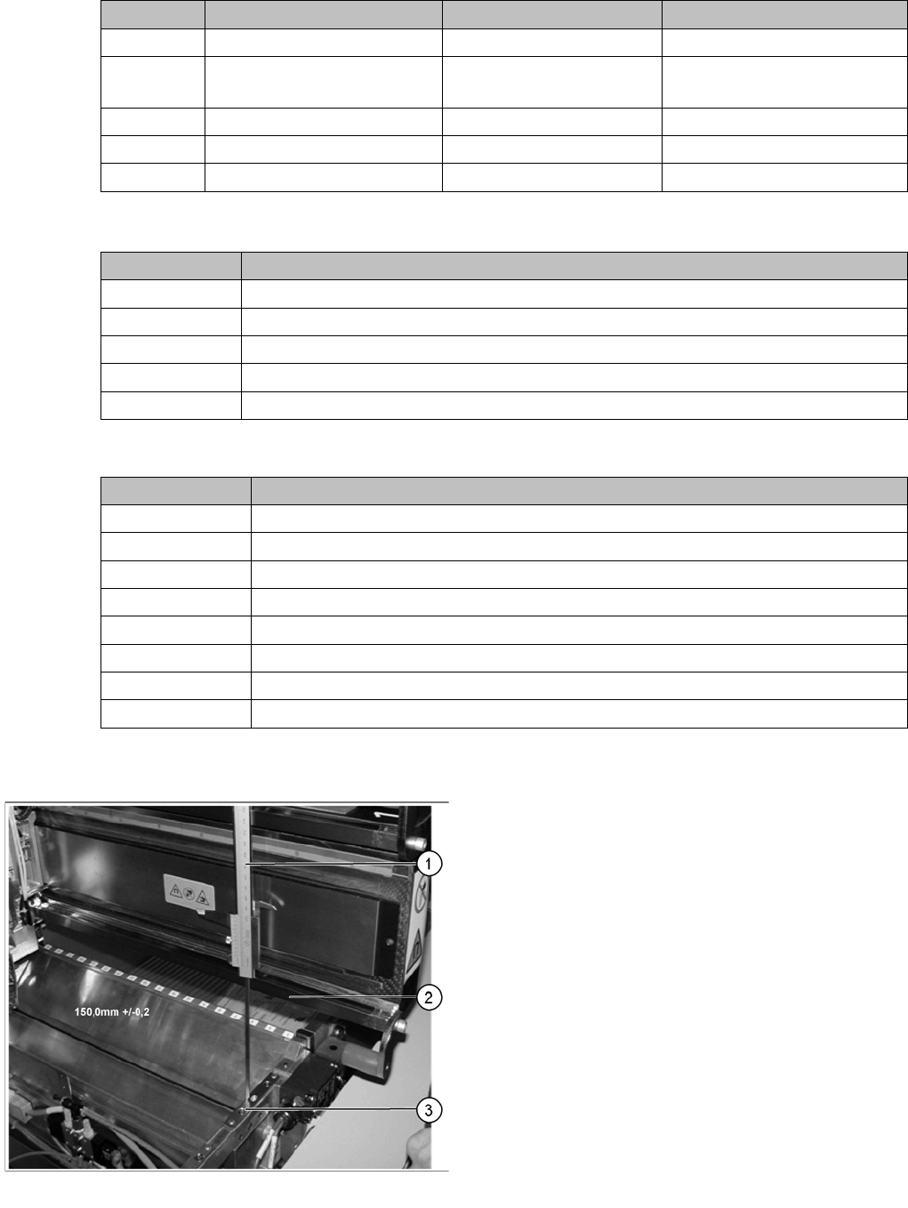
1. Measuring scale
2. Top edge of the X axis lower linear guide
3. Fitting surface for nozzle changer
In order to guarantee the safety gap between the head
(component sensor) and nozzle changer, the contact
surface of the nozzle changer on the docking unit is set to
a distance of 150.0 mm +/-0.2 mm to the X axis linear
guidance, with a measuring scale. The height of the fitting
surface on the docking unit is adjusted with the help of
shim rings. The nozzle changer can then be fitted.
C&P20A
Settings Setting the Jaws for C&P20A
257 Student Guide SIPLACE X-Serie and X4I SW70x (AL2)
Nozzle stati on
7.5.2.1 Nozzle station
The height of the nozzle reject unit must be set to 140.0 +\-0.3 mm. Measurement follows the same
procedure as that for the nozzle changer .
See also
7.5.2 Setting the Nozzle Changer for C&P20A [ ➙ 256]
Setting the Jaws for C&P 20A
7.5.3 Setting the Jaws for C&P20A
Basics
7.5.3.1 Basics
The jaws need to be correctly set, to ensure that the bridge between the raceway and jaws is accurate.
The correct height between the raceway and jaws is achieved by determining the zero point correction
value for the Z axis.
When fitting the jaws at the Z axis, it is possible to rotate the jaws. With the help of the setting gauge,
the correct angle of the jaws to the raceway can be fixed.
NOTICE
Fitting the nozzle changer
When fitting the nozzle changer, make sure that the component reject tray can be removed.
Make sure that the screws you are using are not too long, as these might jam the reject tray.
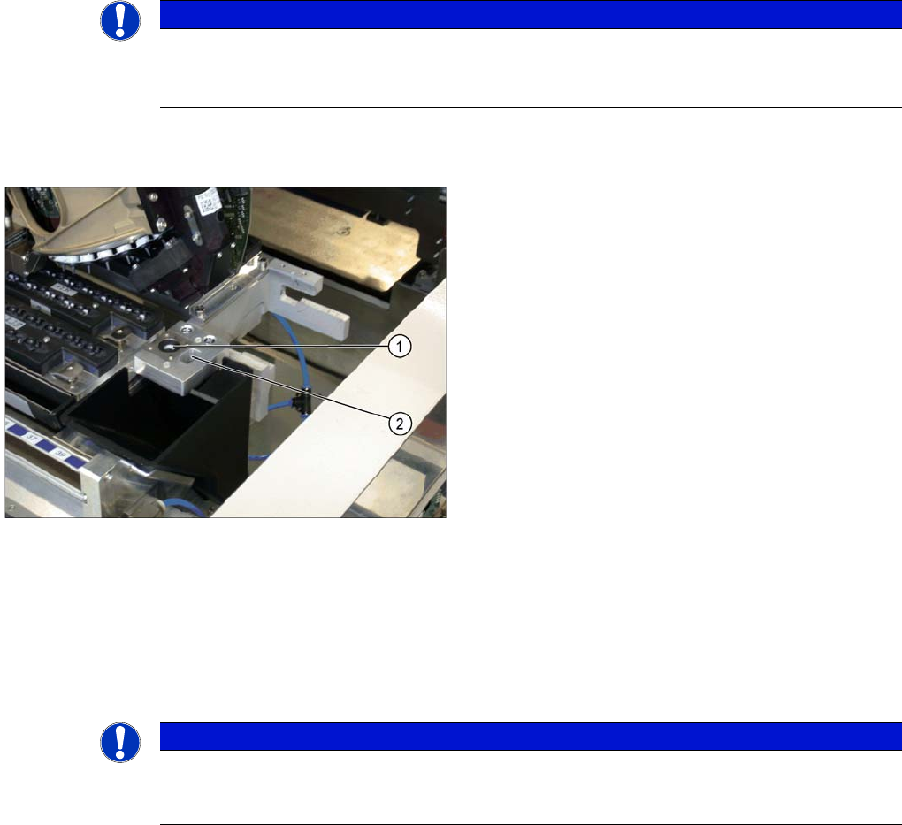
The C&P20 reject unit is equipped with a device for
checking the seat of the nozzles on the segments, after a
nozzle change. The nozzle station also features an air
blast valve, which removes the components externally
with a blast of air. If components are not rejected via the
blast air pulse by the pressure control valve, the
placement head will automatically move to the nozzle
station to reject the components there.
Legend
1. Check nozzle seat
2. Nozzle reject
NOTICE
This service task requires the use of a special tool and may therefore only be performed by
specially trained SIPLACE service technicians. The procedure is described in a separate
manual.