00194614-08 Trainingsdoku. SG X-Serie_X4i SW70x (AL2)_EN.pdf - 第263页
C&P20A Room for Your Sketches and Notes Pneumatic Plan for Nozzle Changer 263 Student Guide SIPLACE X-Serie and X4I SW70x (AL2) {Commented by , XXX: Check!!} Room for Yo u r Sketches and Notes 7.7 Room for Your Sketc…
C&P20A
Pneumatic Plan for Nozzle Changer Nozzle changer
Student Guide SIPLACE X-Serie and X4I SW70x (AL2) 262
The nozzle changer is controlled via a so-called CAN node. This is integrated into the machine CAN bus.
This is integrated into the machine CAN bus.
The CAN Node NC tape cutter
module has the following tasks:
1. Cutter control (see Chapter Component Handling)
2. Nozzle changer control (row 1/2)
3. Valve control in the nozzle station
4. Sensor monitoring at the component and nozzle reject bin
See also
4.3.11 Tape Cutter and Nozzle Changer - Communication [ ➙ 112]
Pneumatic Plan for Nozzle Changer
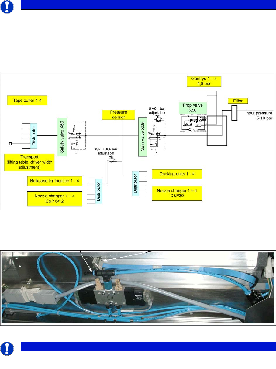
7.6.4 Pneumatic Plan for Nozzle Changer
Compressed air supply for the nozzle changers
The compressed air supply of 4.5 bar for the C&P20 nozzle changer is connected via a T-piece (see
diagram below). The optional 2nd magazine carrier is supplied with compressed air via another Y piece.
(Not for X4I)
Compressed air connection (T-piece) for nozzle changer
NOTICE
Old nozzle changers, which were addressed via the one wire bus, are not able to communicate
via the CAN nodes. The new NC can be addressed via one wire and CAN nodes.
NOTICE
On SX1/2 and SX4 as well as on newer X series machines the FCU is activated at the relevant
location (see chapter Component Handling).

C&P20A
Room for Your Sketches and Notes Pneumatic Plan for Nozzle Changer
263 Student Guide SIPLACE X-Serie and X4I SW70x (AL2)
{Commented by , XXX: Check!!}
Room for You r Sketches and Notes
7.7 Room for Your Sketches and Notes

C&P20A
Pneumatic Plan for Nozzle Changer Room for Your Sketches and Notes
Student Guide SIPLACE X-Serie and X4I SW70x (AL2) 264