00194614-08 Trainingsdoku. SG X-Serie_X4i SW70x (AL2)_EN.pdf - 第272页
Collect, Pick and Place Head (CPP) Overview of Parts Overview Student Guide SIPLACE X-Serie and X4I SW70x (AL2) 272 Component S ensor Funct ions Component Sensor Functions Pickup Process: When the Z axis moves do wnwards…
Collect, Pick and Place Head (CPP)
Overview Overview of Parts
271 Student Guide SIPLACE X-Serie and X4I SW70x (AL2)
Retract unit
8.2.7.4 Retract unit
Retract Un it Functions
Retract Unit Functions
At zero current, the bearing friction of the Z axis is not sufficient to protect the axis from falling down. A
pneumatic retract system has been installed to protect the Z axis should the gantry be moved when the
machine is switched off. This retract unit keeps the Z axis in the safe, upper position during zero current.
Component Sensor
8.2.7.5 Component Sensor
As a default, each CPP head is fitted with a component sensor in the pickup/place position.
This component sensor monitors the presence and/or component height after pickup and before
placement.
The sensor is fixed to the head with two screws and can be replaced as a complete unit during service
work.
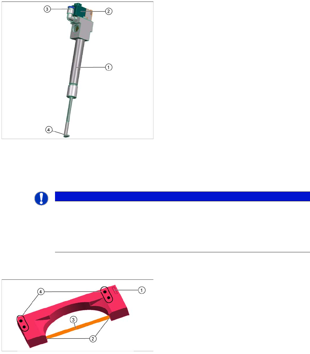
Legend
1. Pneumatic cylinder
2. Solenoid valve
3. Compressed air connection
4. Z axis driver
The retract unit is fixed to the Z axis. This retract unit
keeps the Z axis in the safe, upper position during zero
current. This ensures that the placement head is not
damaged when the machine is switched off or in the
event of a power cut.
The retract unit is not a spare part and can only be
replaced together with the complete front plate of the
head.
NOTICE
The Z axis control system is designed to ensure that, should the machine power supply fail (or
be switched off), there is always enough power temporarily stored by the Z motor servo unit and
axis controller board to move the Z axis to the upper position.
Power failure is recognized by the issuance of a "Power fail" signal. This "Power fail" signal
enables the relevant function (upwards movement of Z axis and activation of the retract unit)
on the axis controller board.
Legend
1. Power/data supply connector
2. Transmitter and receiver unit
3. Laser beam
4. Fixture to head casing
(2x centering pins, 2x screws)
Collect, Pick and Place Head (CPP)
Overview of Parts Overview
Student Guide SIPLACE X-Serie and X4I SW70x (AL2) 272
Component Sensor Functions
Component Sensor Functions
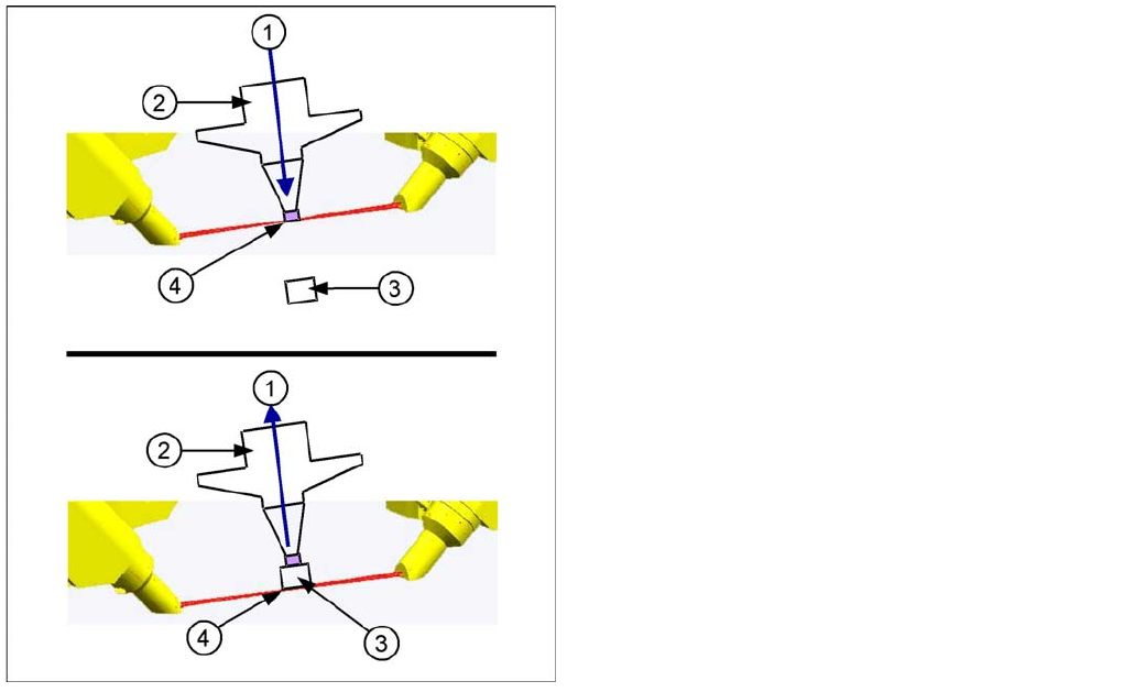
Pickup Process:
When the Z axis moves downwards, the nozzle interrupts the laser beam. At this exact moment, this Z
axis position is read out and compared to the reference value, from the height reference run, or from this
segment after placement. This determines whether there is still a component on the nozzle or not. If the
Z axis position indicates that there is a component on the nozzle, the Z axis will be immediately stopped.
An error message will appear or the component will be rejected and added to the repair cycle as not
placed.
When the Z axis moves upwards again, the laser beam is released and the Z position read out. Based
on the Z position during downwards movement, the system can now determine the presence and height
of a component.
Placement Process:
During the placement process, the system checks whether the component is at the nozzle (Z downwards
movement) or whether placement has been performed on the component (Z upwards movement). As a
precaution, these Z positions are compared to those from the pickup procedure.
This ensures maximum pickup and placement reliability.
Legend
1. Downwards (top diagram) or upwards (bottom
diagram) movement
2. Nozzle
3. Component
4. Reading out the Z position, if the laser beam is
interrupted (top diagram) or has been released again
(bottom diagram).
The component sensor signal is directly linked to the axis
controller (measurement system) of the Z axis. This
enables you to read out the Z position during upwards
and downwards movement.
Collect, Pick and Place Head (CPP)
Overview Overview of Parts
273 Student Guide SIPLACE X-Serie and X4I SW70x (AL2)
Holding Circuit
8.2.7.6 Holding Circuit
Screwed Joint with Collector Ring (for CPP Heads from Version 05)
Screwed Joint with Collector Ring (for CPP Heads from Version 05)
▪ The screwed joint is fixed to the holding circuit. The screwed joint is used to ensure the compressed
air supply to the terminal board and to the holding circuit.
▪ In addition, the screwed joint is fitted with a collector ring which serves as potential equalization
between the stationary and the rotating part of the placement head.
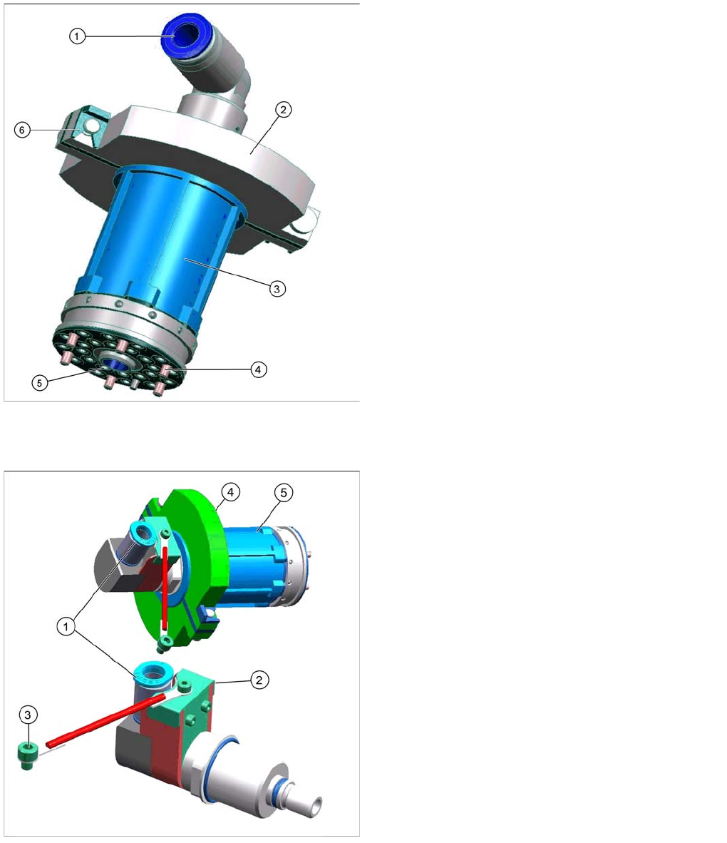
Legend
1. Compressed air inlet 4.5 bar
2. Two part silencer for exhaust air from the venturi
nozzles and fixture for the silencer (6)
3. Casing with venturi nozzles
4. Fixture of holding circuit to star frame
5. Inner drillings: Venturi nozzle inlet (compressed air)
Outer drillings: Vacuum to the segments.
The holding circuit (4) is fixed with six screws to the star
frame. It consists of a venturi block with 12 small venturi
nozzles (5), a silencer (2) and a compressed air
connection (1).
The compressed air inlet feeds the compressed air (min.
4.5 bar) via the valves to the venturi nozzles. Each
venturi nozzle supplies one segment with vacuum in the
hold circuit.
If a segment is in the pickup/placement circuit, the
holding circuit vacuum is increased by the pressure
control valve (for pickup) or eliminated via air blast (for
placement).
Legend
1. Compressed air inlet 4.5 bar
2. Collector ring cover
3. Grounding connection to the front plate
4. Silencer
5. Holding circuit