00194614-08 Trainingsdoku. SG X-Serie_X4i SW70x (AL2)_EN.pdf - 第274页
Collect, Pick and Place Head (CPP) Overview of Parts Overview Student Guide SIPLACE X-Serie and X4I SW70x (AL2) 274 Star 8.2.7.7 Star The star consists of t he star frame, on which the 12 DP drives are located, the contr…
Collect, Pick and Place Head (CPP)
Overview Overview of Parts
273 Student Guide SIPLACE X-Serie and X4I SW70x (AL2)
Holding Circuit
8.2.7.6 Holding Circuit
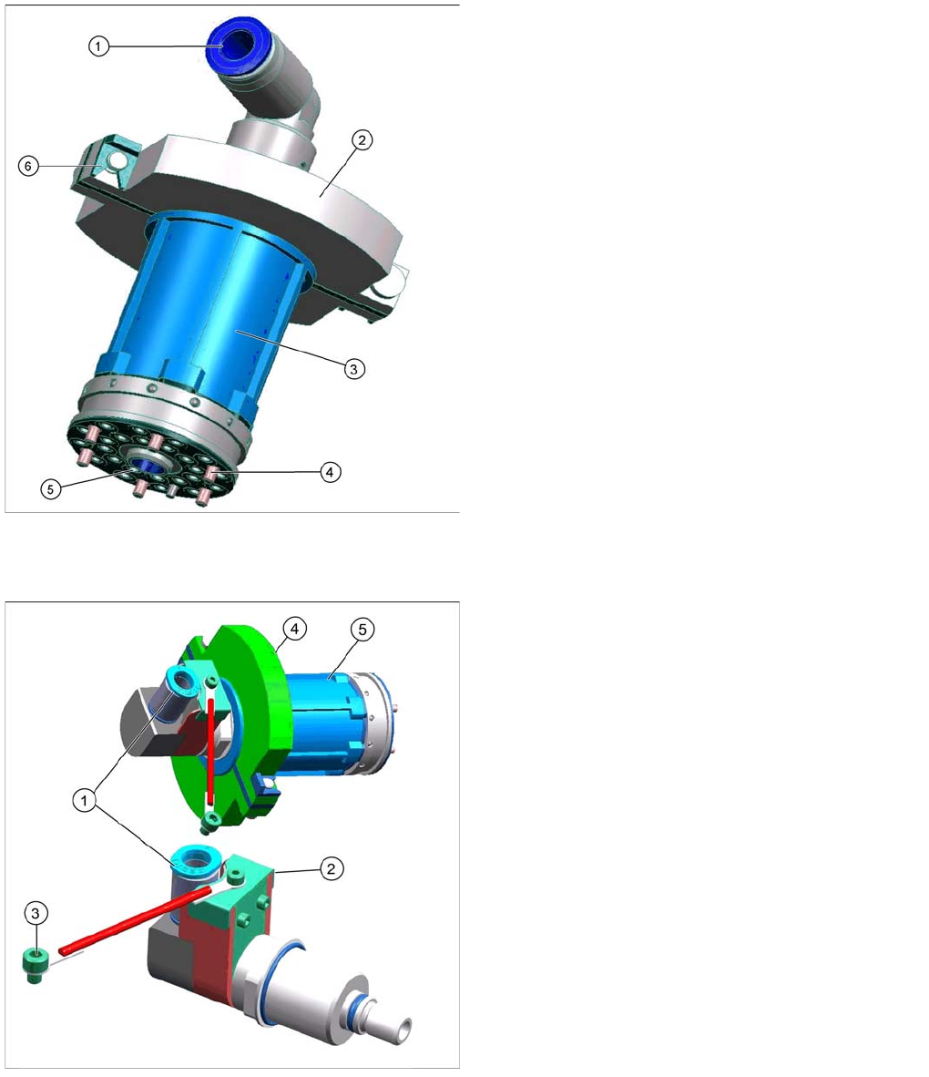
Screwed Joint with Collector Ring (for CPP Heads from Version 05)
Screwed Joint with Collector Ring (for CPP Heads from Version 05)
▪ The screwed joint is fixed to the holding circuit. The screwed joint is used to ensure the compressed
air supply to the terminal board and to the holding circuit.
▪ In addition, the screwed joint is fitted with a collector ring which serves as potential equalization
between the stationary and the rotating part of the placement head.
Legend
1. Compressed air inlet 4.5 bar
2. Two part silencer for exhaust air from the venturi
nozzles and fixture for the silencer (6)
3. Casing with venturi nozzles
4. Fixture of holding circuit to star frame
5. Inner drillings: Venturi nozzle inlet (compressed air)
Outer drillings: Vacuum to the segments.
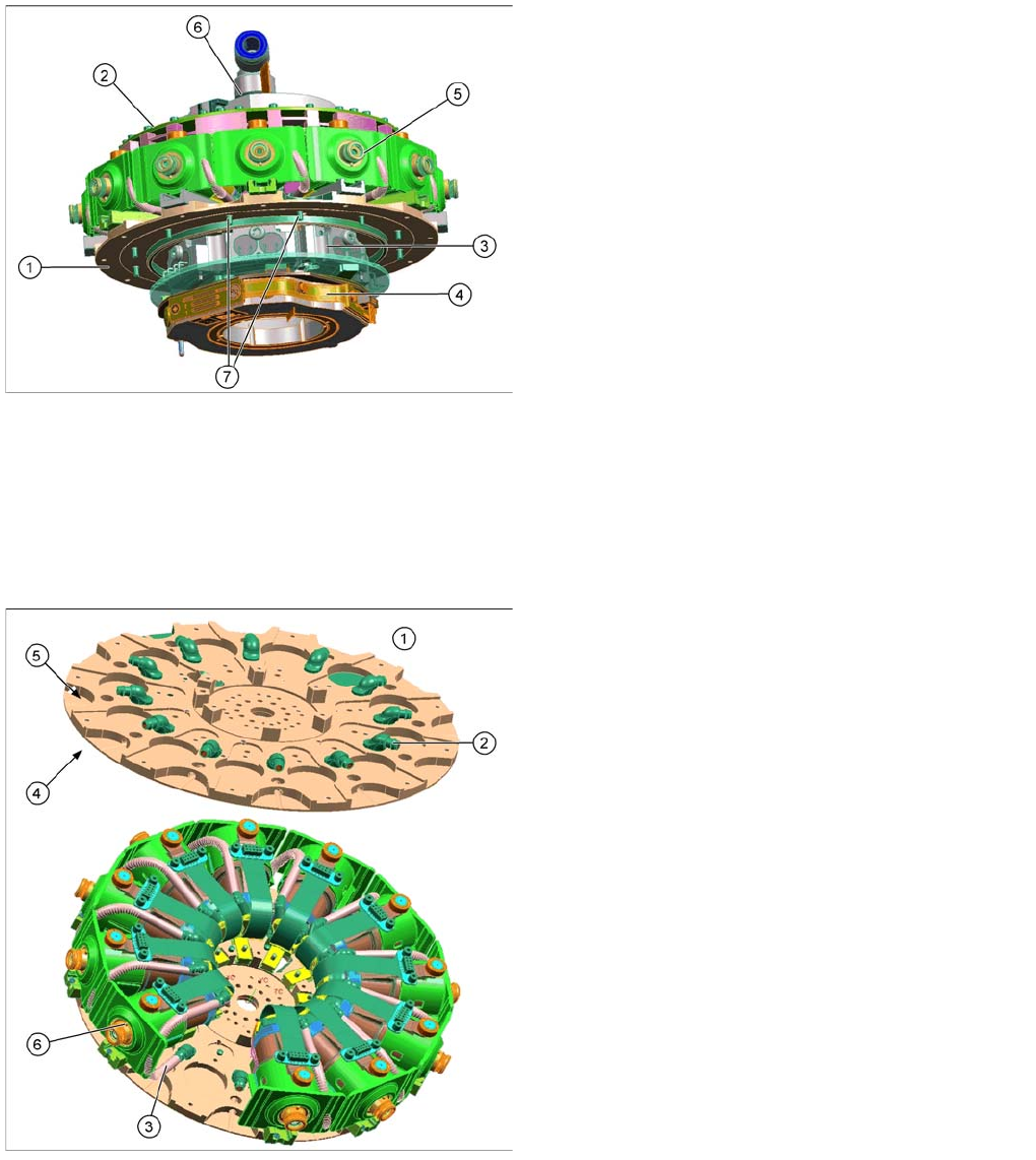
The holding circuit (4) is fixed with six screws to the star
frame. It consists of a venturi block with 12 small venturi
nozzles (5), a silencer (2) and a compressed air
connection (1).
The compressed air inlet feeds the compressed air (min.
4.5 bar) via the valves to the venturi nozzles. Each
venturi nozzle supplies one segment with vacuum in the
hold circuit.
If a segment is in the pickup/placement circuit, the
holding circuit vacuum is increased by the pressure
control valve (for pickup) or eliminated via air blast (for
placement).
Legend
1. Compressed air inlet 4.5 bar
2. Collector ring cover
3. Grounding connection to the front plate
4. Silencer
5. Holding circuit
Collect, Pick and Place Head (CPP)
Overview of Parts Overview
Student Guide SIPLACE X-Serie and X4I SW70x (AL2) 274
Star
8.2.7.7 Star
The star consists of the star frame, on which the 12 DP drives are located, the control board (Single Core
Solution), the valve terminal and the E/D transformer.
The holding circuit is in the center of the star.
The complete unit is fixed to the rotor of the star motor.
Star Frame
8.2.7.8 Star Frame
Legend
1. Star frame
2. Single Core Solution
3. Valve terminal
4. E/D transformer (CPP heads up to version 04)
5. DP drives
6. Holding circuit in the middle of the star
7. Fixture on rotor of star motor
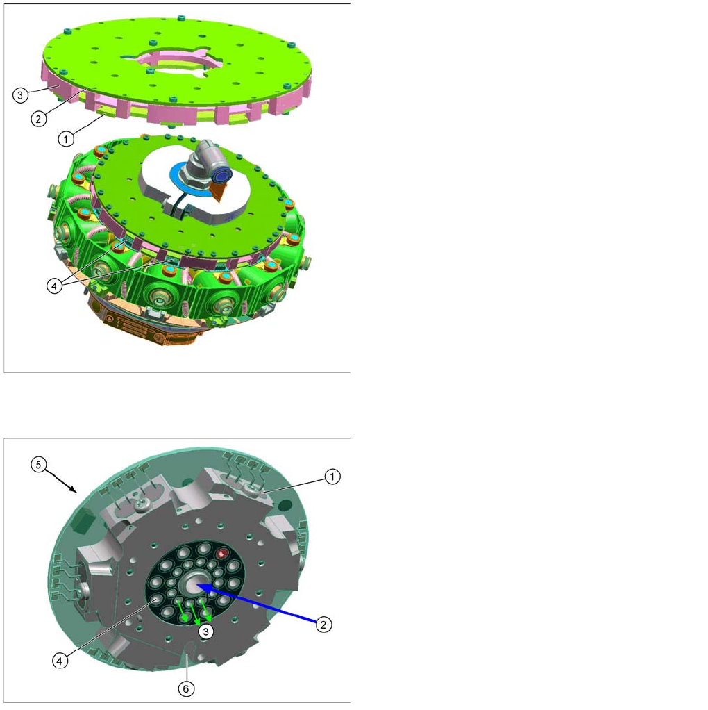
Legend
1. Star frame
2. Star frame plate
3. Hose to DP drive
4. Back of the star frame
5. Front of the star frame
6. DP drive
The star frame plate is fixed directly to the rotor of the star
motor.
The valve terminal and the E/D transformer are fixed to
the back of the star frame.
The twelve DP drives are fixed to the front and the
holding circuit with control unit (SCS) is fixed to the
center.
The vacuum or air blast is fed via the holding circuit
through the star frame plate to the individual DP drives
(through a hose).
Collect, Pick and Place Head (CPP)
Overview Overview of Parts
275 Student Guide SIPLACE X-Serie and X4I SW70x (AL2)
Single Core Solution (SCS)
8.2.7.9 Single Core Solution (SCS)
Valve term inal
8.2.7.10 Valve terminal
The valve terminal consists of 12 valves (1), one for each segment.
The compressed air from the holding circuit (2) is distributed over 12 channels for the 12 segments. Each
of these channels has a valve. This enables the compressed air to be switched on or off for each
segment (3).
This means, after a component has been placed, the compressed air can be switched off for this
segment.
Before picking up a component, the compressed air is switched on again and vacuum is present at the
nozzle via the holding circuit with venturi nozzles. The disconnection of compressed air after placement
reduces the compressed air per placement head by approx. 40-50%.
The outer channels (4) are used to measure the holding circuit and supply the air blast or vacuum for the
pickup/placement circuit via the pressure control valve.
Legend
1. Board control module
2. Board power module
3. Carrier plate
4. Connector for data and power supply to the DP drives
The SCS has two main tasks:
1. Controlling the DP drives
2. Evaluating the Z down light barrier.
The assembly consists of a carrier plate and two boards
(control module and power module).
The power and data supply is via the head CAN bus from
the intermediate distributor, E/D transformer to the SCS.
The SCS features 12 connectors, which establish the
connection for the power and data supply to the DP
drives.
Legend
1. Valve (12x)
2. Compressed air from holding circuit
3. Inner channels - compressed air for the segments
4. Outer channels
5. Contact free data transfer (receiver)
6. Flexprint for energy and data transfer to SCS