00194614-08 Trainingsdoku. SG X-Serie_X4i SW70x (AL2)_EN.pdf - 第276页
Collect, Pick and Place Head (CPP) Overview of Parts Overview Student Guide SIPLACE X-Serie and X4I SW70x (AL2) 276 Holding Ci rcuit Val ve Functio ns Holding Circuit Valve Functions E/D Transformer (for CPP Heads < V…
Collect, Pick and Place Head (CPP)
Overview Overview of Parts
275 Student Guide SIPLACE X-Serie and X4I SW70x (AL2)
Single Core Solution (SCS)
8.2.7.9 Single Core Solution (SCS)
Valve term inal
8.2.7.10 Valve terminal
The valve terminal consists of 12 valves (1), one for each segment.
The compressed air from the holding circuit (2) is distributed over 12 channels for the 12 segments. Each
of these channels has a valve. This enables the compressed air to be switched on or off for each
segment (3).
This means, after a component has been placed, the compressed air can be switched off for this
segment.
Before picking up a component, the compressed air is switched on again and vacuum is present at the
nozzle via the holding circuit with venturi nozzles. The disconnection of compressed air after placement
reduces the compressed air per placement head by approx. 40-50%.
The outer channels (4) are used to measure the holding circuit and supply the air blast or vacuum for the
pickup/placement circuit via the pressure control valve.
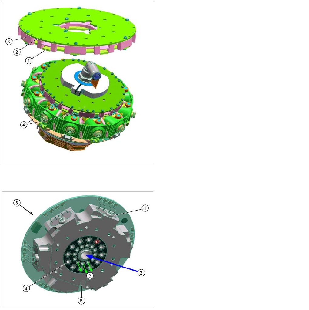
Legend
1. Board control module
2. Board power module
3. Carrier plate
4. Connector for data and power supply to the DP drives
The SCS has two main tasks:
1. Controlling the DP drives
2. Evaluating the Z down light barrier.
The assembly consists of a carrier plate and two boards
(control module and power module).
The power and data supply is via the head CAN bus from
the intermediate distributor, E/D transformer to the SCS.
The SCS features 12 connectors, which establish the
connection for the power and data supply to the DP
drives.
Legend
1. Valve (12x)
2. Compressed air from holding circuit
3. Inner channels - compressed air for the segments
4. Outer channels
5. Contact free data transfer (receiver)
6. Flexprint for energy and data transfer to SCS
Collect, Pick and Place Head (CPP)
Overview of Parts Overview
Student Guide SIPLACE X-Serie and X4I SW70x (AL2) 276
Holding Circuit Valve Functions
Holding Circuit Valve Functions
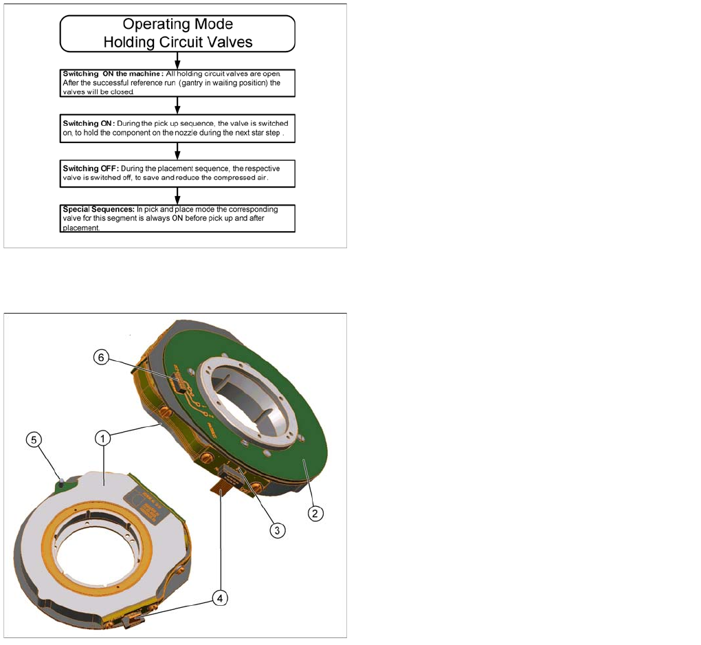
E/D Transformer (for CPP Heads < Version 05)
8.2.7.11 E/D Transformer (for CPP Heads < Version 05)
▪ The energy and data transformer consists of a stationary and a rotating part.
▪ The three sliding contacts transmit the direct current voltage (24V/4A).
▪ Communication (the transmission of CAN Bus signals) is contactless. The transmitter is located on
the rear cover of the CPP head and the receiver module on the valve terminal.
▪ The connector (4) supplies power from the intermediate distributor.
▪ The centering pin fixes the stationary part in place via the rear cover of the CPP head.
▪ The rotating part is fixed with five screws to the valve terminal.
▪ The valve terminal consists of 12 holding circuit
valves, which can be switched independently at any
time and in any star position.
▪ Switching on the valves means “throughput”:
Compressed air is present at the venturi nozzles
(voltage = 0V). If a valve should fail or if it is without a
voltage supply, vacuum is always present at the
holding circuit.
▪ Switching off the valves means “valve closed”: There
is no compressed air present at the venturi nozzle
(24 V voltage is present). This saves compressed air!
Legend
1. Stationary part
2. Rotating part
3. Sliding contacts (3x)
4. Connector for power supply
5. Centering pin
6. Interface to valve terminal
Collect, Pick and Place Head (CPP)
Overview Overview of Parts
277 Student Guide SIPLACE X-Serie and X4I SW70x (AL2)
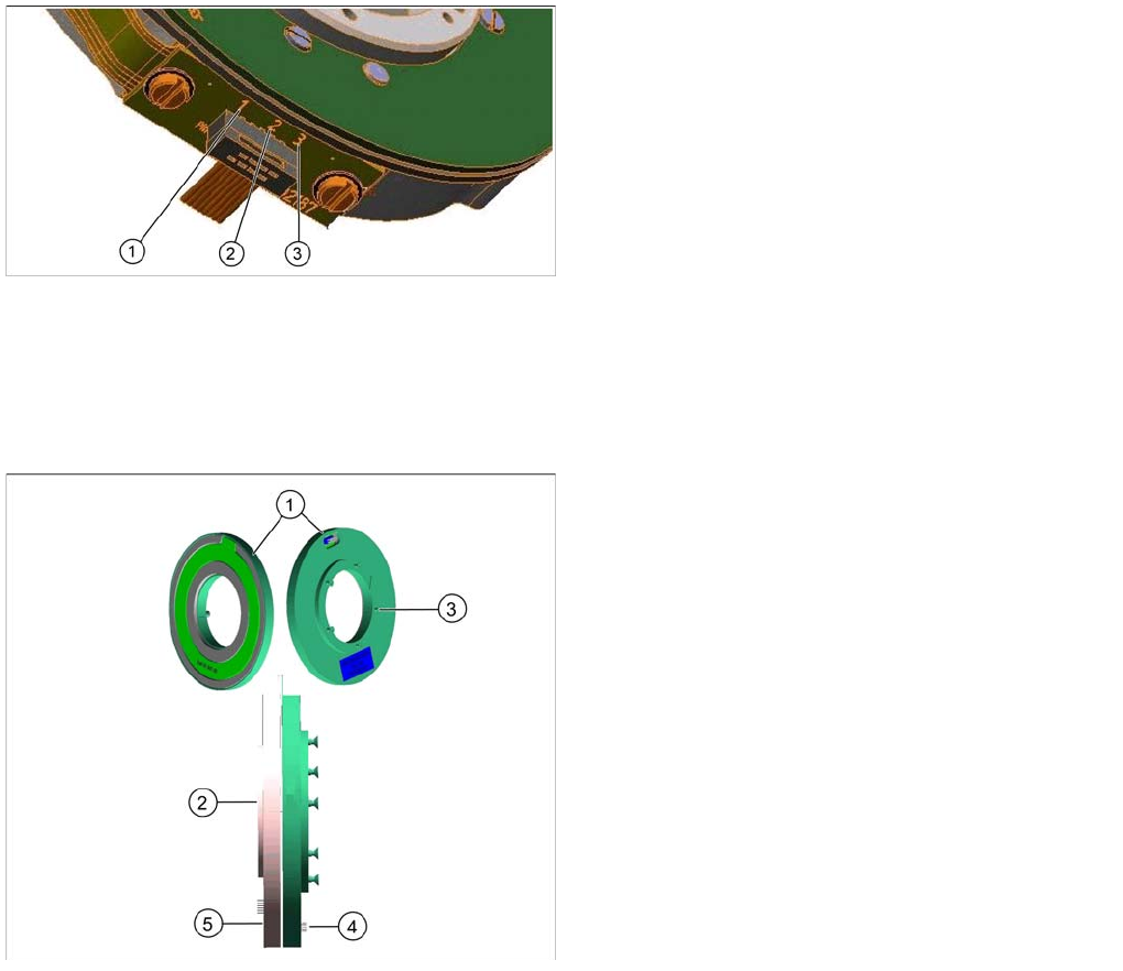
Energy Transmission
Energy Transmission
▪ Two transmission leads are needed to transmit the energy supply: P24V (1) and GND (2).
▪ Another lead (3) (sliding contact) forms the connection between the rotating part and the housing
ground (ESD protection).
Contactless Energy Transformer (for CPP Heads from Version 05)
8.2.7.12 Contactless Energy Transformer (for CPP Heads from Version 05)
▪ The contactless energy transformer consists of two parts, a stator (1) and a rotor (2).
▪ Activating is done via an additional board that is located on the intermediate distributor 2 as a
piggyback board.
▪ The stator is fixed at the rear cover of the placement head, the rotating part, rotor, (2) is fixed to the
star frame via the terminal board.
▪ In the middle of the contactless energy transformer the transformer for contactless data transmission
is located.
Legend
1. P24V
2. GND
3. ESD protection
Legend
1. Stationary part (stator)
2. Rotating part (rotor)
3. Fastening screw at the rear cover (5x)
4. Power supply from the intermediate distributor to the
stator
5. Centering pin
6. Connector to SCS