00194614-08 Trainingsdoku. SG X-Serie_X4i SW70x (AL2)_EN.pdf - 第283页
Collect, Pick and Place Head (CPP) Overview Vacuum System 283 Student Guide SIPLACE X-Serie and X4I SW70x (AL2) Vacuum System 8.2.8 Vacuum System Legend (1) Compressed air distributor (2) Holding circuit sensor (3) Rear …
Collect, Pick and Place Head (CPP)
Overview of Parts Overview
Student Guide SIPLACE X-Serie and X4I SW70x (AL2) 282
Intermedia te Distributor
8.2.7.16 Intermediate Distributor
Component camera
8.2.7.17 Component camera
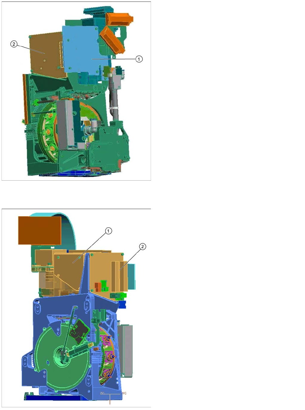
Legend
The intermediate distributor consists of two boards:
1. Intermediate distributor 1 is fitted to the front of the
head.
2. Intermediate distributor 2 is fitted to the left side of the
head.
Functions of the intermediate distributor:
▪ LEDs show the operating voltages at the head and
the state of the sensors
▪ Test connector for the track signals and test pins for
analog signals
▪ Controlled power supply for incremental encoder
from Z and star drive
▪ Interface for component sensor, vacuum unit, holding
circuit vacuum sensor and EEPROM
▪ Startup control for the return cylinder
Legend
1. Component camera
2. Intermediate distributor 2
Component - camera (SST29 / ST38)
The component camera is fitted in the 12.00 position, as
in the case of the C&P6/12 heads.
This camera is responsible for optically recognizing the
component and for calculating its centerpoint.
The component camera evaluates the data determined
and calculates the offset between the component
centerpoint and the nozzle centerpoint plus the angle in
the placement position.
Collect, Pick and Place Head (CPP)
Overview Vacuum System
283 Student Guide SIPLACE X-Serie and X4I SW70x (AL2)
Vacuum System
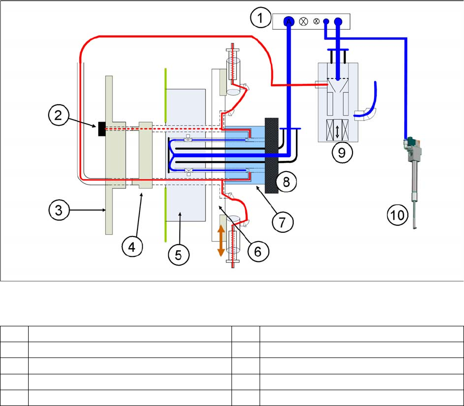
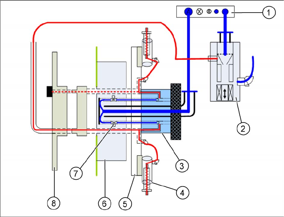
8.2.8 Vacuum System
Legend
(1) Compressed air distributor (2) Holding circuit sensor
(3) Rear cover – CPP head (4) Smooth distributor disc
(5) Valve terminal (6) Star frame with DP drives
(7) Holding circuit (8) Silencer
(9) Pressure control valve (digital) (10) Z axis return cylinder
Collect, Pick and Place Head (CPP)
Vacuum System Overview
Student Guide SIPLACE X-Serie and X4I SW70x (AL2) 284
Vacuum System Function
8.2.8.1 Vacuum System Function
▪ The pneumatic distributor (1) supplies the pressure control valve (2), the holding circuit (3) and the
return cylinder with 4.5 bar compressed air.
▪ The compressed air is fed directly through the holding circuit (3) to the valve terminal (6). There it is
distributed into 12 channels.
▪ Each channel in the holding circuit can be separately opened or closed with a solenoid valve (7).
▪ The compressed air is fed from the valve terminal to the holding circuit, through the 12 channels. The
vacuum for the holding circuit of all 12 segments is generated there via 12 venturi nozzles.
▪ The vacuum is fed from the holding circuit via the star frame (5) to the nozzle segment (4).
▪ The holding circuit sensor is located in the CPP head cover (8). The holding circuit sensor can be
used to measure the vacuum of any segment which is in the 12 position.