00194614-08 Trainingsdoku. SG X-Serie_X4i SW70x (AL2)_EN.pdf - 第285页
Collect, Pick and Place Head (CPP) Overview Vacuum System 285 Student Guide SIPLACE X-Serie and X4I SW70x (AL2) Picking Up Component s 8.2.8.2 Picking Up Components Placing Co mponents 8.2.8.3 Placing Components Before t…
Collect, Pick and Place Head (CPP)
Vacuum System Overview
Student Guide SIPLACE X-Serie and X4I SW70x (AL2) 284
Vacuum System Function
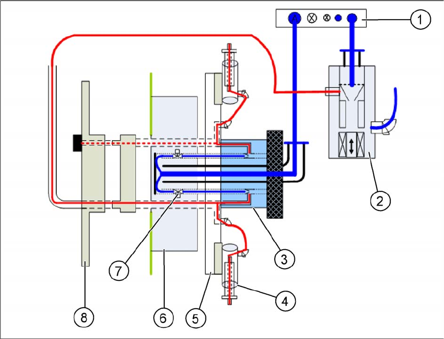
8.2.8.1 Vacuum System Function
▪ The pneumatic distributor (1) supplies the pressure control valve (2), the holding circuit (3) and the
return cylinder with 4.5 bar compressed air.
▪ The compressed air is fed directly through the holding circuit (3) to the valve terminal (6). There it is
distributed into 12 channels.
▪ Each channel in the holding circuit can be separately opened or closed with a solenoid valve (7).
▪ The compressed air is fed from the valve terminal to the holding circuit, through the 12 channels. The
vacuum for the holding circuit of all 12 segments is generated there via 12 venturi nozzles.
▪ The vacuum is fed from the holding circuit via the star frame (5) to the nozzle segment (4).
▪ The holding circuit sensor is located in the CPP head cover (8). The holding circuit sensor can be
used to measure the vacuum of any segment which is in the 12 position.
Collect, Pick and Place Head (CPP)
Overview Vacuum System
285 Student Guide SIPLACE X-Serie and X4I SW70x (AL2)
Picking Up Components
8.2.8.2 Picking Up Components
Placing Components
8.2.8.3 Placing Components
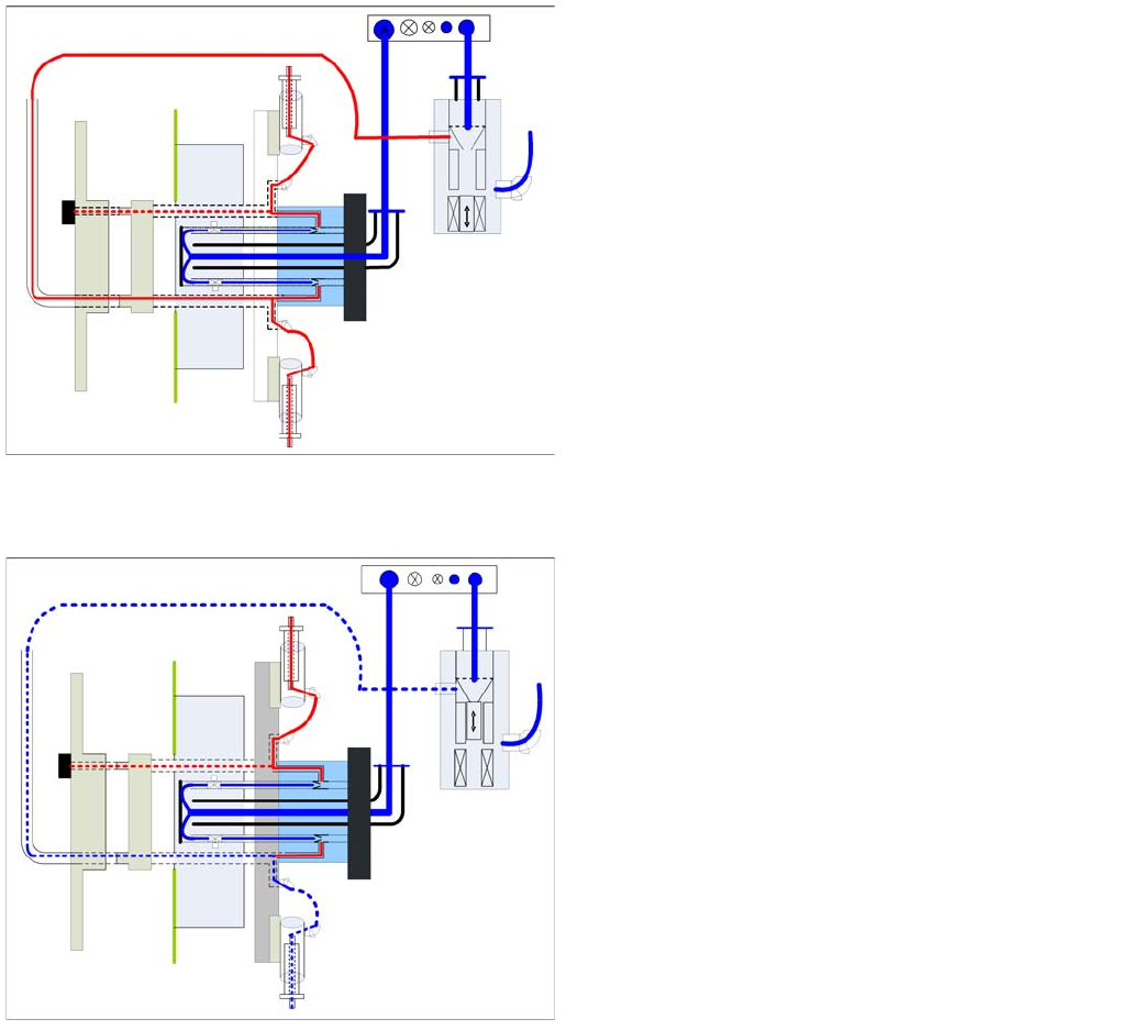
Before the star rotates into the pickup position, the
relevant valve is switched on via the valve terminal.
Vacuum from the holding circuit is now present at the
nozzle.
Once the star has reached the pickup position, the
holding circuit vacuum is strengthened via the pressure
control valve and the component can be picked up.
▪ After the component has been picked up, the
component is held on the nozzle with the help of the
vacuum from the holding circuit.
▪ If the star is in the placement position and the Z down
sensor is enabled, the pressure control valve will
switch over to air bast. This eliminates the holding
circuit vacuum and an air blast of approx. 200 mbar is
present at the nozzle.
▪ The switch on time for max. vacuum/air blast
depends on the settings programmed in the
programming system.
▪ Once the Z axis has reached the top position, the star
continues to turn. The relevant valve is now closed on
the valve terminal. This saves compressed air!
Collect, Pick and Place Head (CPP)
Vacuum System Reference Run CPP Head
Student Guide SIPLACE X-Serie and X4I SW70x (AL2) 286
Reference Run CPP Head
8.3 Reference Run CPP Head
Reference run CPP head
Description
The CPP head has a Z axis, a star axis and twelve
independent DP axes. All these axes need to be
initialized before placement begins. This ensures that the
control system knows where their actual mechanical
position is.
When the software is started, the embedded software
checks all subsystems and sends the result to the
superior control software.
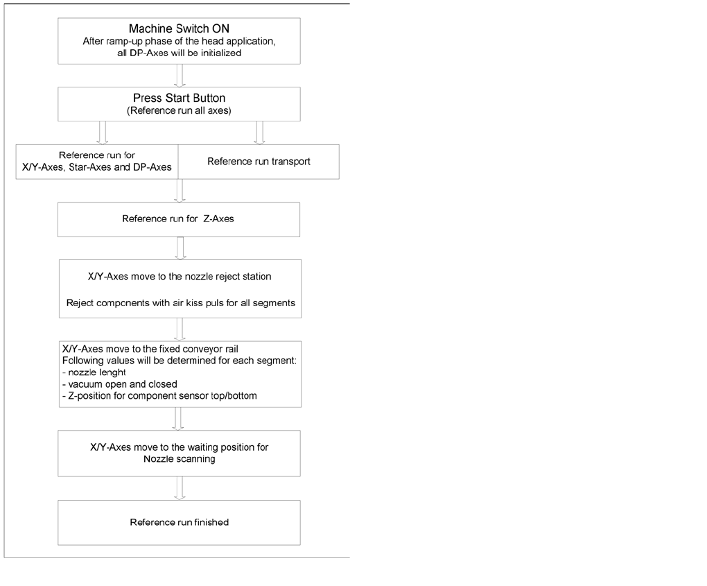
The reference run is started by pressing the start button
(see adjacent flow diagram). The processes have been
optimized as far as possible and can run parallel to one
another (star and DP axes plus initialization of conveyor).