00194614-08 Trainingsdoku. SG X-Serie_X4i SW70x (AL2)_EN.pdf - 第296页
Collect, Pick and Place Head (CPP) Board Recognition - Centering t he Board Fiducials Pickup and Pla cement Cycle for CPP Student Guide SIPLACE X-Serie and X4I SW70x (AL2) 296 Board R ecognition - Centering the B oard Fi…
Collect, Pick and Place Head (CPP)
Pickup and Placement Cycle for CPP Board Position Recognition
295 Student Guide SIPLACE X-Serie and X4I SW70x (AL2)
Board P osition Re cognition
8.4.3 Board Position Recognition
We differentiate between standard position recognition and dual position recognition.
PCB – position recognition (standard position recognition)
Board position recognition is used to determine the exact position of the board in the machine (conveyor
--> placement area).
PCB position recognition is performed with gantry 4 for placement area 1 and with gantry 2 in placement
area 2.
There should be at least two fiducials on each PCB. These are then used to calculate the X/Y position
and the rotary angle of the board, in the conveyor system.
The fiducials should not be on the same line.
Up to 3 fiducials can be programmed for position recognition. With this third fiducial you can also
determine and correct any displacement within the board (shrinkage, stretched).
Dual position recognition (for alternating mode only)
Dual position recognition is required in order to guarantee the placement accuracy. Materials change
according to the temperature they are subjected to and the same applies to the machine gantries.
Dual position recognition is performed with gantry 1 in placement area 1 and with gantry 3 in placement
area 2.
In the case of dual position recognition, gantry 1/3 uses the fiducial position recognition values from
gantry 2/4 to calculate the placement offset for gantry 1/3. Depending on the arrangement of fiducials on
the board, either 2 or 3 fiducials will be used for dual position recognition.
The fiducials for dual position recognition are selected so that the calculation performed can be as
accurate as possible.
Temperature compensation
A further measure to ensure placement accuracy is the temperature compensation with the help of
sensors on the head plate. The head plate features two temperature sensors, the temperature values of
which are regularly checked via a separate bus system.
The software uses these temperature values to calculate an offset value, which is added to the head
offset.
▪ Head offset SW 60x is the distance PCB <--> component camera
▪ Head offset SW 70x is the distance PCB camera <--> nozzle tip
▪ The temperature reference value is the temperature during the last machine calibration.
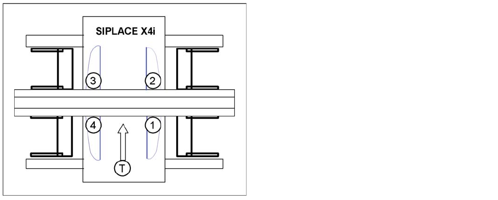
SIPLACE X4I:
▪ Gantry 4 – position recognition with max. 3 fiducials
▪ Gantry 2 – position recognition with 2 fiducials
▪ Gantries 1 and 3 – dual position recognition
Legend
▪ 1: Gantry 1
▪ 2: Gantry 2
▪ 3: Gantry 3
▪ 4: Gantry 4
▪ T = Transport direction
Collect, Pick and Place Head (CPP)
Board Recognition - Centering the Board Fiducials Pickup and Placement Cycle for CPP
Student Guide SIPLACE X-Serie and X4I SW70x (AL2) 296
Board R ecognition - Centering the B oard Fiducials
8.4.4 Board Recognition - Centering the Board Fiducials
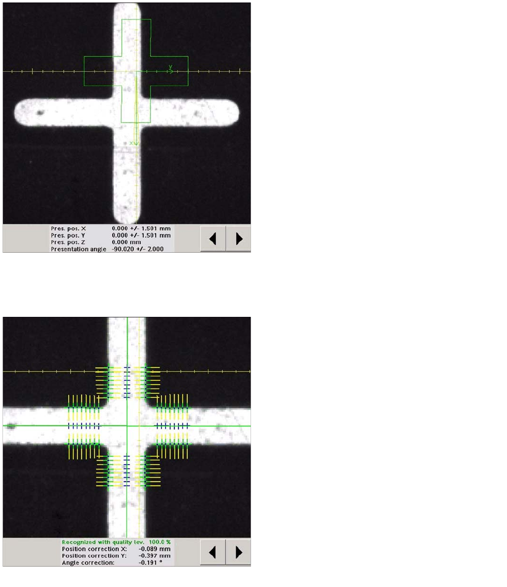
Board recognition run to target position of board
The fiducial is expected at this target position. The PCB
camera is moved from waiting position to this fiducial
position.
▪ Board position recognition is performed before the
first component is picked up.
▪ The gantry axes move the PCB camera to the
theoretical fiducial position. The camera takes the
picture of the first fiducial and the Vision system
calculates the center position.
Board recognition - centering the board fiducials
The centered fiducial now defines the actual position of
the board.
▪ The camera records an image of the 2nd fiducial and
the Vision system calculates the center position of
this image.
▪ The 2nd calculation is the deviation between the
target and the calculated fiducial position.
▪ All board fiducials are optically centered with this
procedure.
▪ This data is sent to the machine controller.
▪ Corrected values are now calculated for the X,Y and
angular position of the board.
▪ The gantry axes now move the placement head to the
first pickup position.
Collect, Pick and Place Head (CPP)
Pickup and Placement Cycle for CPP Turning Nozzles 1 to 12 to the Pickup Angle (0° or 90°)
297 Student Guide SIPLACE X-Serie and X4I SW70x (AL2)
Turning Nozzles 1 to 12 to the Pick up Angle (0° or 90°)
8.4.5 Turning Nozzles 1 to 12 to the Pickup Angle (0° or 90°)
Procedure for Picking Up Components
8.4.6 Procedure for Picking Up Components
Prerequisite: The nozzle must be in the correct pickup position (0° or 90°).
1. The gantry moves over the pickup position of the 1st component.
2. Valve 1 of the valve terminal is switched on.
3. Vacuum measurement in pickup/place circuit „open“
4. The Z axis travels down and interrupts the component sensor.
5. The Z position is read out, the nozzle length calculated and compared to the reference length from
the height reference run.
1. The vacuum is switched on (pressure control valve - either "early vacuum" or with light barrier down,
depending on the pickup profile.)
2. The Z axis moves up. A vacuum check is performed to determine whether there is a component on
the nozzle.
3. The component sensor is released and the Z position is read out. Either the component height is
calculated or a presence check is performed.
4. A vacuum check is performed when the Z axis is in the top position.
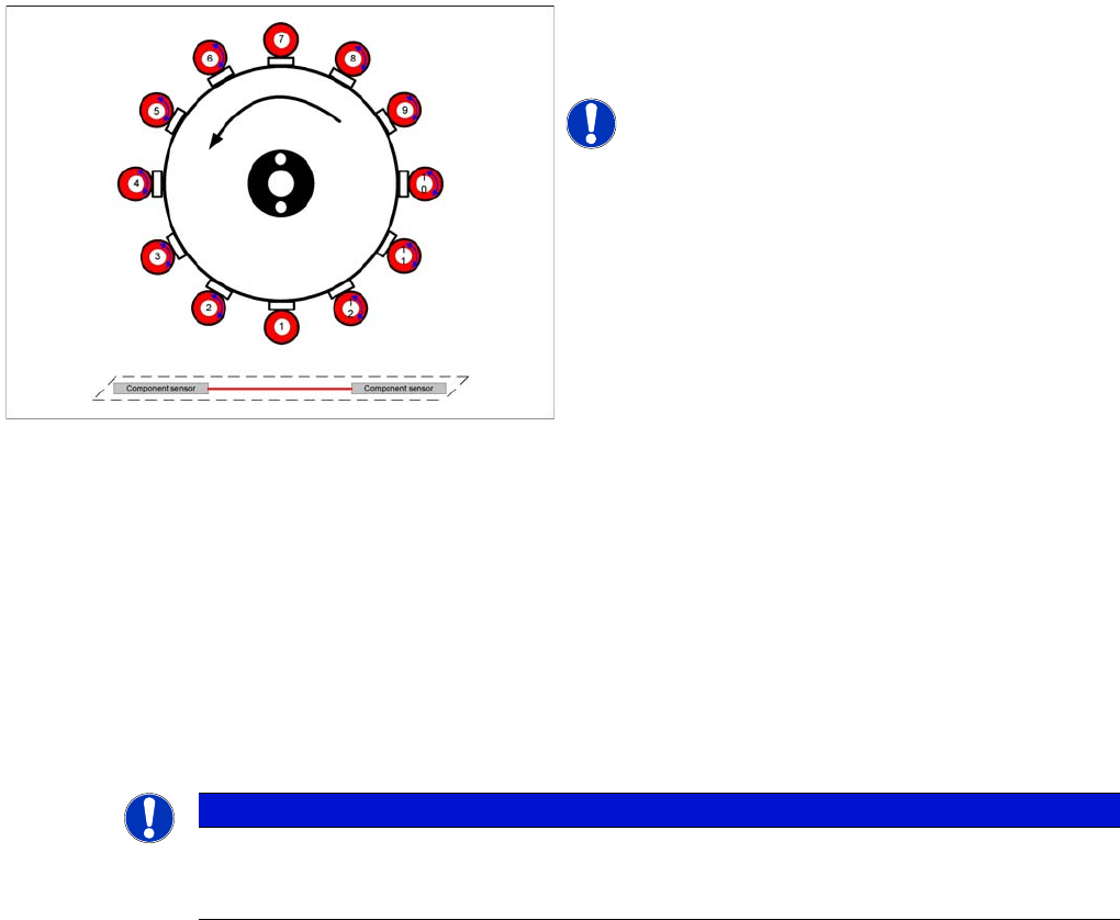
5. The star is rotated and more components are picked up.
6. The component on segment 1 is rotated into the placement position by the DP drive (area A).
7. A component is picked up at segment 7.
8. The component at segment 1 is optically centered under the component camera.
9. A placement angle correction run is performed after optical centering (area B).
10. Once all 12 components have been picked up, the pickup process has finished.
Turning segments 1 to 12 to the pickup angle (0° or 90°)
▪ The segments in the CPP head are turned in
succession, from segment 1 to 12, to the required
pickup angle of 0° or 90°.
NOTICE! Each segment has its own DP drive
NOTICE
This calculated nozzle length is used when moving up in the placement cycle, to check whether
the component is placed. If a length difference of -0.15 mm or +0.1 mm is found, a warning will
be issued: Replace nozzles.