00194614-08 Trainingsdoku. SG X-Serie_X4i SW70x (AL2)_EN.pdf - 第309页
Collect, Pick and Place Head (CPP) Settings on the CPP Head Board Descriptions 309 Student Guide SIPLACE X-Serie and X4I SW70x (AL2) Control Module Intermedia te Distributor 1 8.5.1.5 Intermediate Distributor 1 LEDs on I…

Collect, Pick and Place Head (CPP)
Board Descriptions Settings on the CPP Head
Student Guide SIPLACE X-Serie and X4I SW70x (AL2) 308
Status LED
red
LED
green
7
segm
ent
Comment
De-energized Off Off 8 LEDs and 7-segment display off
Download ZDS (Z down sensor /
Z bottom sensor)
Flash
es
Flash
es
LEDs flash alternately with high frequency
Download SCS 8 Visualisation via 7-segment display
Waiting for baud rate detection
(baud rate has not been
detected yet)
8 Visualisation via 7-segment display
Error during baud rate detection 8 Visualisation via 7-segment display
CAN error (error frames) 8 Visualisation via 7-segment display
SCS application is missing
(BIOS active)
8 Visualisation via 7-segment display
ZDS application is missing
(BIOS active)
Flash
es
Off Red LED flashes
Error in application 2
e. g. leff error
Off Off Red LED shines permanently
Z down sensor not initialized Flash
es
Off Red LED flashes
DP is referenced but encoder
error line is set
Flash
es
On Red LED flashes / Green LED shines
Z down sensor –
no communication
Off Off LEDs off
DP drive operation at positioning Off On If green shines this means that the drive is in
position regulation. LED off means that the
drive has just performed an action (no end
position signal).
ZDS is ready for operation but
the drive has not been
referenced
Off Flash
es
Green LED flashes
Open Flash
es
Off Red LED flashes rapidly
Open Off Flash
es
Green LED flashes rapidly
Collect, Pick and Place Head (CPP)
Settings on the CPP Head Board Descriptions
309 Student Guide SIPLACE X-Serie and X4I SW70x (AL2)
Control Module
Intermedia te Distributor 1
8.5.1.5 Intermediate Distributor 1
LEDs on Inte rmediate Dis tributor 1
LEDs on Intermediate Distributor 1
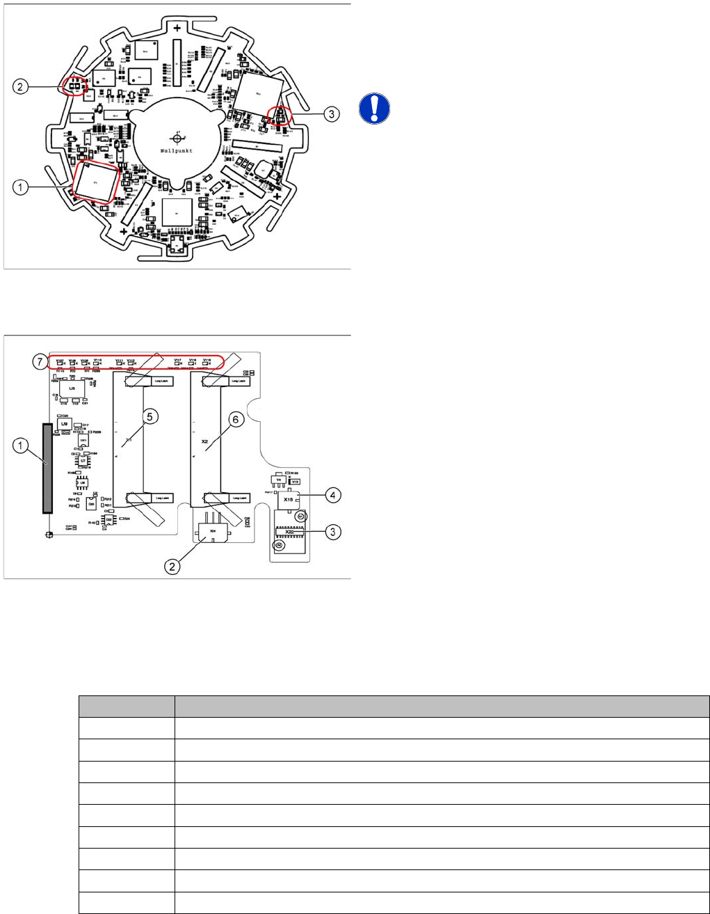
Legend
1. 16 bit processor
2. H1 and H2
3. H3
NOTICE! The status LEDs are not visible, as the
control module is located behind the power module!
Legend
The intermediate distributor 1 establishes the connection
to the intermediate distributor 2 and the adapter board.
Furthermore, the following sensors and actuators of the
CPP head are directly plugged in here.
1. X25 – Connector to intermediate distributor 2
2. X24 – Z motor
3. X22 – Connector Z axis encoder (track signals) with
EEPROM
4. X15 – Return cylinder
5. X1 – Connector for flat ribbon cable to the head
adapter
6. X2 – Connector for flat ribbon cable to the head
adapter
7. LEDs
LED Meaning
V106 Operating voltage +15 V
V107 Operating voltage + 5 V
V108 Operating voltage -15 V
V111 Z axis encoder error
V112 Star axis encoder error
V115 Operating voltage +24 V_DP/3.3V_DP
V116 Status of pressure control valve
V117 Z_down sensor "ON"
V118 Return cylinder moved out
Collect, Pick and Place Head (CPP)
Board Descriptions Settings on the CPP Head
Student Guide SIPLACE X-Serie and X4I SW70x (AL2) 310
Intermedia te Distributor 2
8.5.1.6 Intermediate Distributor 2
Address ing the Contactle ss Energy Transfo rmer
Addressing the Contactless Energy Transformer
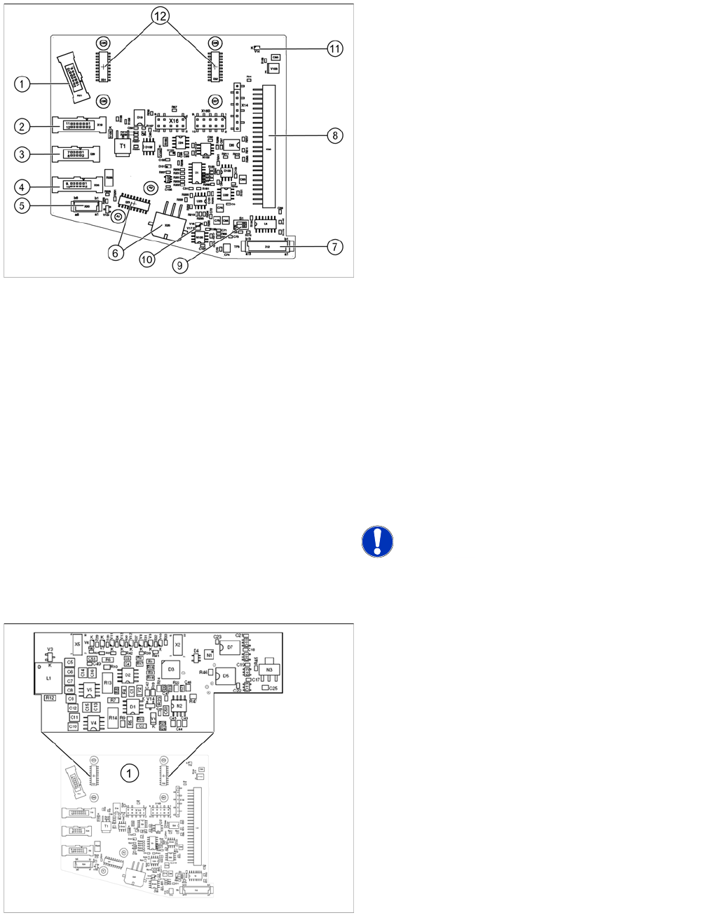
Legend
The following sensors and actuators for the CPP head
are connected to the intermediate distributor using plug-
and socket connections:
1. X21 – Component sensor
2. X19 – Vacuum sensor holding circuit
3. X29 – Energy transmission collector ring (24 V) (CPP
head < version 05)
4. X26 – Energy transmission (contactless) CPP head
from version 05
5. X20 –Not in use
6. X23 – Connector star encoder (track signals) with
EEPROM, X25 star motor
7. X12 – Digital pressure control valve
8. X30 – Connector to intermediate distributor 1
9. Switch S1.1: CAN test
Switch S1.2: CAN ID
Set both switches to OFF.
10. V17/V18 – Potential display, voltage present
11. 24 V – DP 24 V switched
12. X31,X32 connector for the board addressing the
contactless energy transformer (CPP head from
version 05)
X14, X16, X16B: Test connector CAN Bus
X27, X28: Test connector for FPGA
NOTICE! Either X20, X26 or X29 is used!
For contactless energy transmission an additional board
is plugged onto the intermediate distributor 2.
Legend
1. X31/X32 - connector for addressing the contactless
energy transformer.
Description of the LEDs:
V6 – Maximum current exceeded
V7 – Continuous current too high
V9 – Addressing of contactless energy transformer
switched on
V10 – Error, contactless energy transformer switched off
The green LED V9 lights in normal operation