00194614-08 Trainingsdoku. SG X-Serie_X4i SW70x (AL2)_EN.pdf - 第311页
Collect, Pick and Place Head (CPP) Settings on the CPP Head Converting the CPP Head for a Different Head Heig ht 311 Student Guide SIPLACE X-Serie and X4I SW70x (AL2) Convertin g the CPP Head fo r a Different Head Height…
Collect, Pick and Place Head (CPP)
Board Descriptions Settings on the CPP Head
Student Guide SIPLACE X-Serie and X4I SW70x (AL2) 310
Intermedia te Distributor 2
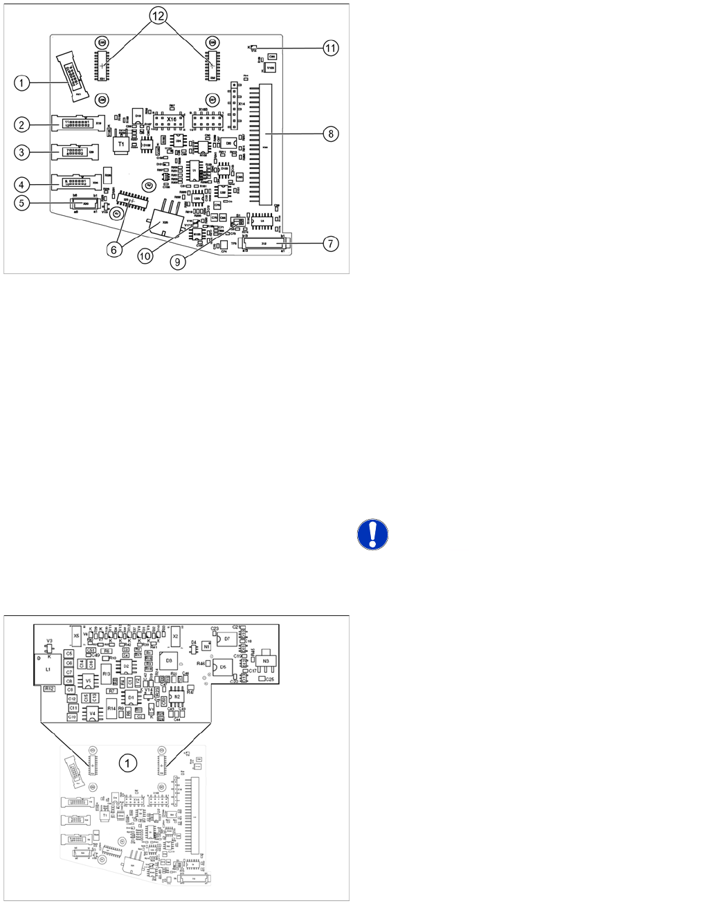
8.5.1.6 Intermediate Distributor 2
Address ing the Contactle ss Energy Transfo rmer
Addressing the Contactless Energy Transformer
Legend
The following sensors and actuators for the CPP head
are connected to the intermediate distributor using plug-
and socket connections:
1. X21 – Component sensor
2. X19 – Vacuum sensor holding circuit
3. X29 – Energy transmission collector ring (24 V) (CPP
head < version 05)
4. X26 – Energy transmission (contactless) CPP head
from version 05
5. X20 –Not in use
6. X23 – Connector star encoder (track signals) with
EEPROM, X25 star motor
7. X12 – Digital pressure control valve
8. X30 – Connector to intermediate distributor 1
9. Switch S1.1: CAN test
Switch S1.2: CAN ID
Set both switches to OFF.
10. V17/V18 – Potential display, voltage present
11. 24 V – DP 24 V switched
12. X31,X32 connector for the board addressing the
contactless energy transformer (CPP head from
version 05)
X14, X16, X16B: Test connector CAN Bus
X27, X28: Test connector for FPGA
NOTICE! Either X20, X26 or X29 is used!
For contactless energy transmission an additional board
is plugged onto the intermediate distributor 2.
Legend
1. X31/X32 - connector for addressing the contactless
energy transformer.
Description of the LEDs:
V6 – Maximum current exceeded
V7 – Continuous current too high
V9 – Addressing of contactless energy transformer
switched on
V10 – Error, contactless energy transformer switched off
The green LED V9 lights in normal operation
Collect, Pick and Place Head (CPP)
Settings on the CPP Head Converting the CPP Head for a Different Head Height
311 Student Guide SIPLACE X-Serie and X4I SW70x (AL2)
Convertin g the CPP Head fo r a Different Head Height
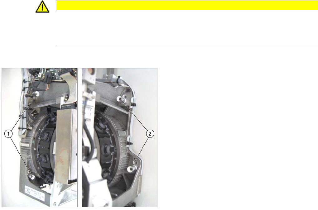
8.5.2 Converting the CPP Head for a Different Head Height
Overview
CAUTION
The placement head can be installed on two different heights. CPP_L corresponds to a
component height of 6 mm. CPP_H corresponds to a component height of 11.5 mm.
If the CPP head is used in a placement area with stationary camera, TwinHead or MTC, it may
only be used in the upper position.
Legend
1. Fastening screws on the left side
2. Fastening screws on the right side
In this graphic the fastening screws are shown in the
"head top" position.
Collect, Pick and Place Head (CPP)
Calibrating the Segment Offset Settings on the CPP Head
Student Guide SIPLACE X-Serie and X4I SW70x (AL2) 312
Conversion
Calibrating the Segment Offset
8.5.3 Calibrating the Segment Offset
► Switch over to the operator level Machine Service.
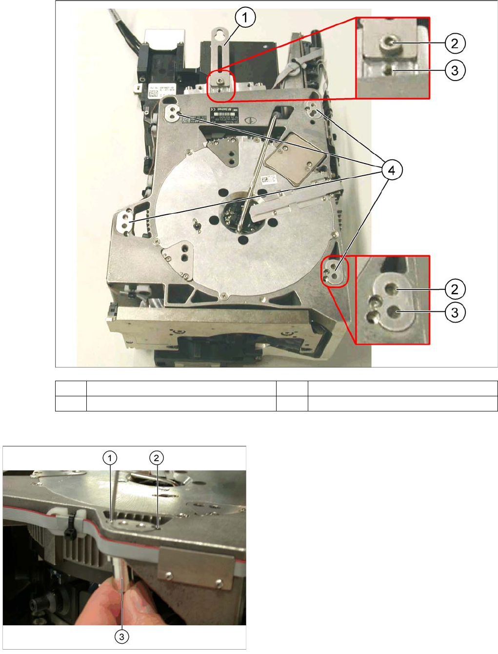
(1) Holding bracket (2) "Head bottom" position
(3) "Head top" position (4) Fixture holes with bushings
Legend
1. Drilling for the fastening screw of the bushing in "head
bottom" position
2. Drilling for the fastening screw of the bushing in "head
top" position
3. Bushing"
All four bushings must either be fixed in top or bottom
position.
Proceed as follows when replacing the bushings:
► Undo the fastening screws of the bushings.
► Insert the bushings in the correct position and re-
tighten them.
► Perform these steps for all four bushings and the
holding bracket of the head.