00194614-08 Trainingsdoku. SG X-Serie_X4i SW70x (AL2)_EN.pdf - 第324页
TwinHead Height Reference R un Reference Run Student Guide SIPLACE X-Serie and X4I SW70x (AL2) 324 Height R eference Run 9.2.3 Height Reference Run Vacuum Check 9.2.4 Vacuum Check ▪ After the CAN bus proc essor for the v…
TwinHead
Reference Run Reference Run at Z Axis
323 Student Guide SIPLACE X-Serie and X4I SW70x (AL2)
Referen ce Run at Z Axis
9.2.1 Reference Run at Z Axis
Referenc e Run at D- axis
9.2.2 Reference Run at D- axis
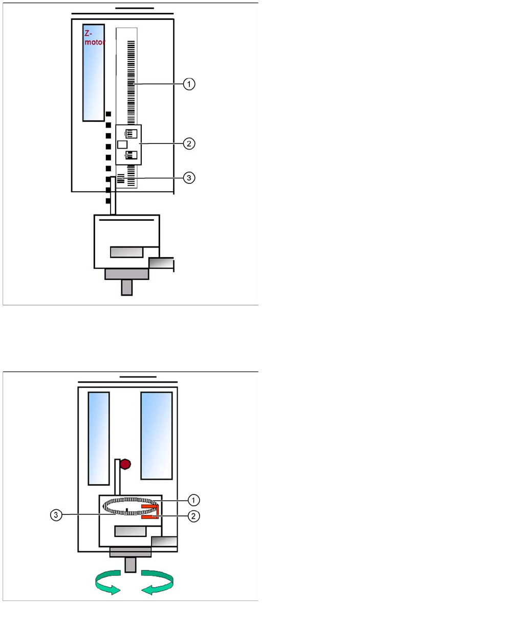
Reference run Z axis
Legend
1. Incremental scale mounted on moveable part of the Z
Axis
2. Fixed Incremental encoder
3. Zero pulse on the incremental scale (only one on the
Z axis)
▪ Z Axis search for the commutation point of the linear
motors (in a special mode because of the danger of a
movement downwards). (A 3 phase motor continues
to run at the correct time and in the correct sequence,
when the current is switched from one phase to the
next one.)
▪ Then the Z Axis move upwards to the Zero pulse and
load the zero point correction.
▪ The zero point correction, max. and min. travel range,
are determined when you calibrate the head height.
Reference run D-axis
Legend
1. Incremental glass scale D-axis
2. Incremental encoder
3. Zero pulse on the incremental glass scale
Then the D-axis (turning axis) executes the reference
run.
The D-axis runs to the zero pulse of the D- axis encoder.
The zero point correction value will be loaded. The D-axis
moves to the reference position, in accordance with the
prefix shown before the value.
Reference run completed! This is followed by the gantry
reference run (see Section Gantry).
TwinHead
Height Reference Run Reference Run
Student Guide SIPLACE X-Serie and X4I SW70x (AL2) 324
Height R eference Run
9.2.3 Height Reference Run
Vacuum Check
9.2.4 Vacuum Check
▪ After the CAN bus processor for the vacuum/air blast distributor has booted, the vacuum/air blast
distributor is initialized. This means that vacuum/air blast generator is adjusted to ensure that neither
vacuum or air blast is generated at the nozzle.
▪ The gantry axes move the TwinHead to the reject position.
▪ Over the reject box the vacuum-, air blast generator switch to air blast to reject components and
check the air blast.
▪ The vacuum/air blast generator now switches over to vacuum and the open vacuum at both
segments (X, SX and D3 machine, D1: one Twin segment) is measured*.
▪ After measurement, the pressure is adjusted back to 0 bar.
▪ The vacuum reference run has now been completed for the TwinHead.
* The closed vacuum value for the Twin segments relates to the calibration value.
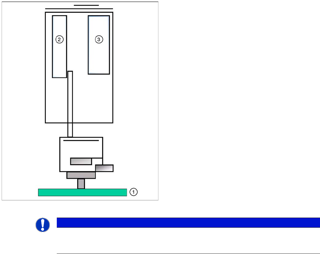
Measuring the nozzle height
With this function we check the correct nozzle type which
is programmed. The nozzle length is taken to calculate
the pick up and placement height for the following
placements.
Legend
1. Top of fixed conveyor side
2. Z motor
3. Vacuum - air blast distribution
► The gantry moves the placement heads above the
fixed conveyor side.
► The Z axis positions module 2 (X/D3 machine)
downwards.
► The travel range of the Z axis is taken to calculate the
TwinHead height in relation to the nozzle type.
► Now the same happen with module 1.
► The maximum length tolerance is 0.4 mm: If the
length difference is too high an error message is
displayed.
NOTICE
Both modules are measured at the same position of the PCB conveyor!
This TwinHead reference run is performed parallel to the C&P heads reference run in other
placement areas.
TwinHead
TwinHead Pickup and Place Cycle General
325 Student Guide SIPLACE X-Serie and X4I SW70x (AL2)
TwinHead Pickup and Place Cycle
9.3 TwinHead Pickup and Place Cycle
General
9.3.1 General
TwinHead Placement Principle
9.3.2 TwinHead Placement Principle
During the PCB transport time, the gantry waits at the theoretical fiducial position, to perform board
centering (and inkspot recognition) after PCB clamping. With the " Whispering down the machine"
option, gantry 3 only evaluates 2 fiducials.
First the TwinHead starts to collect one component with module 1 and one component with module 2.
These components are then centered with the IC camera (FC camera) and placed.
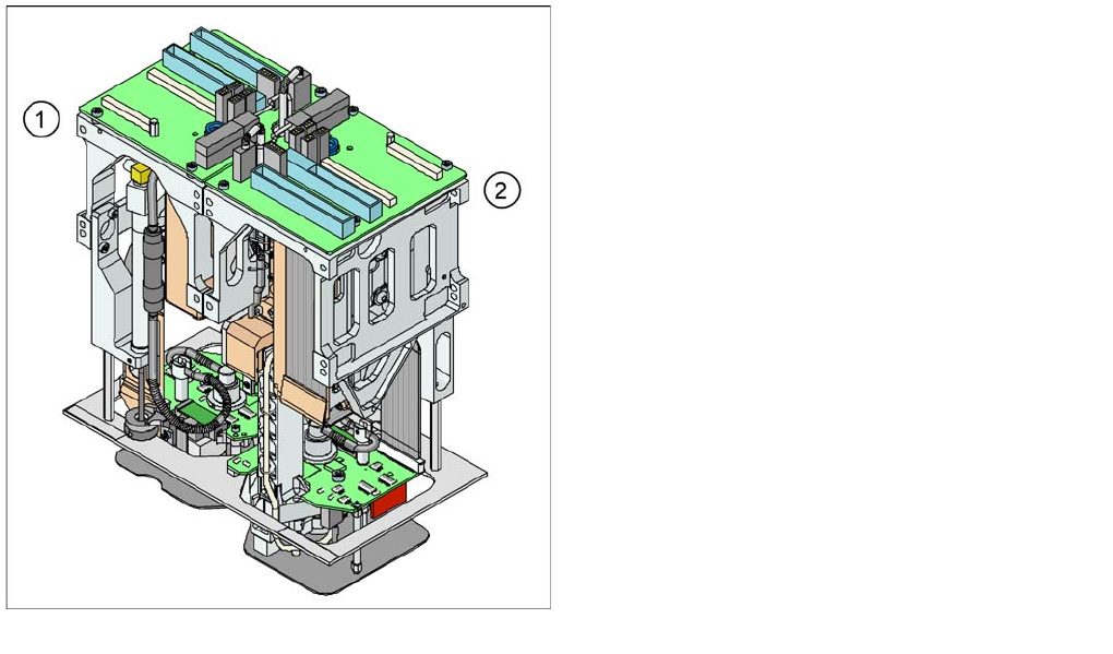
View of TwinHead
The TwinHead module 2 (2) has been mounted at an
angle of 180 degrees to module 1 (1).
▪ The distance between the nozzles is approximately
71 mm in X - direction.
▪ The maximum component height is 25 mm.
▪ The contact force at placement can be programmed
between 0.5 N and 15 N (up to 30 N for a highforce
TwinHead).
▪ The rotational accuracy is 0.07 degrees, 4 sigma/X
and Y axes 35 µm 4 sigma.
▪ The placement of special shaped components has
been improved: