00194614-08 Trainingsdoku. SG X-Serie_X4i SW70x (AL2)_EN.pdf - 第329页
TwinHead TwinHead Pickup and Place Cycle Compo nent centering module 1 and 2 329 Student Guide SIPLACE X-Serie and X4I SW70x (AL2) Component c entering module 1 and 2 9.3.5 Component center ing module 1 and 2 Preparatio …
TwinHead
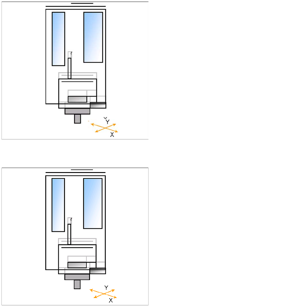
Preparations for Component Pickup (Module 2) TwinHead Pickup and Place Cycle
Student Guide SIPLACE X-Serie and X4I SW70x (AL2) 328
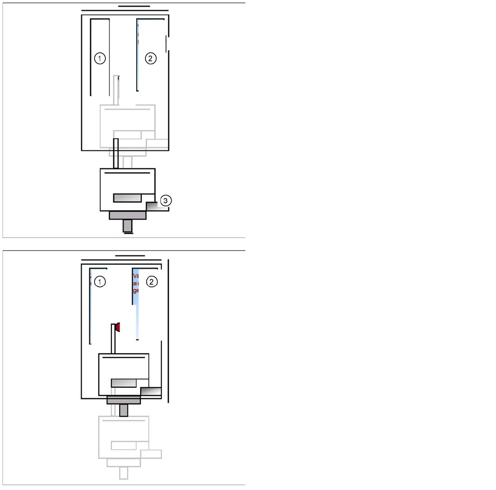
Picking up the Component (Module 2)
9.3.4.1 Picking up the Component (Module 2)
Legend
1. Z motor
2. Vacuum/air blast generator
3. Force sensor
▪ Z Axis position downwards with Standard Pick up
mode at 2 N Pick up force.
▪ At contact with the component the force increase up
to the programmed value.
▪ At this force level the End signal is triggered and the
Vacuum controlling is activated.
Legend
1. Z motor
2. Vacuum/air blast generator
▪ When Vacuum threshold ‘Pick up’ is measured the Z
Axis movement upwards start with Standard-
positioning mode.
▪ Communication to comp. table ‘index Feeder’ when
the Z Axis reached the "safety height" position.
▪ At end signal Z Axis top -> Vacuum check ‘comp. on
nozzle’
▪ The D-axis is rotated to the placement angle (so that
only the component correction angle needs to be
rotated after centering).
▪ Optical centering with module 1 is being prepared
TwinHead
TwinHead Pickup and Place Cycle Component centering module 1 and 2
329 Student Guide SIPLACE X-Serie and X4I SW70x (AL2)
Component centering module 1 and 2
9.3.5 Component centering module 1 and 2
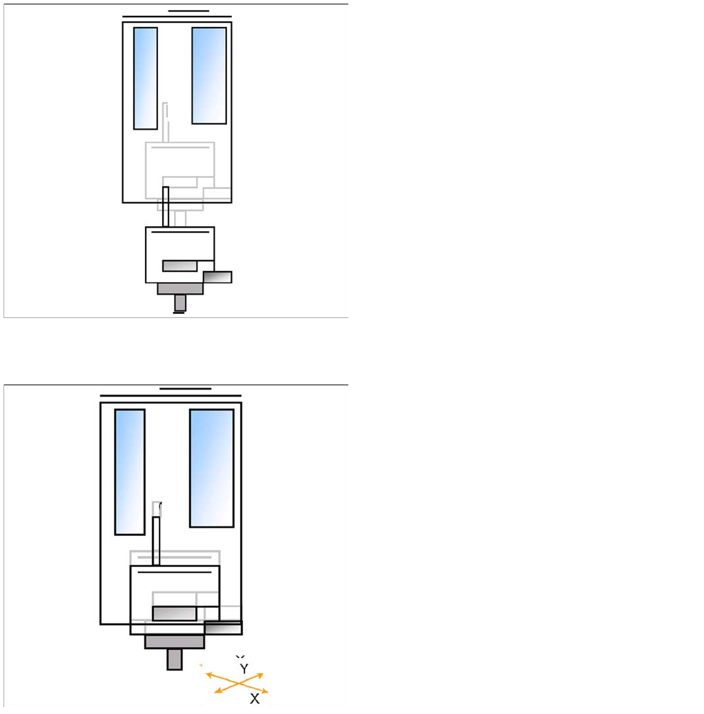
Preparations for Placement (Module 1 Component)
9.3.6 Preparations for Placement (Module 1 Component)
▪ X/Y axes position module 1 via the IC camera.
▪ Z axis moves until the underside of the components
lies in the focus level.
▪ IC-camera illumination is activated.
▪ Move Z Axis again upwards.
▪ Centering 1st component (near placement angle) is
finished
▪ The X/Y axes position module 2 over the IC camera.
▪ Z axis moves until the underside of the components
lies in the focus level.
▪ IC-camera illumination is activated.
▪ Move Z Axis again upwards.
▪ The X/Y gantry axes move to the corrected
placement position.
▪ The D-axis rotates by the placement angle correction
value.
TwinHead
Preparations for Placement (Module 2 Component) TwinHead Pickup and Place Cycle
Student Guide SIPLACE X-Serie and X4I SW70x (AL2) 330
Placement (Module 1 Component)
9.3.6.1 Placement (Module 1 Component)
Preparations for Placement (Module 2 Component)
9.3.7 Preparations for Placement (Module 2 Component)
▪ The Z axis moves downwards in standard mode (2 N
contact force).
▪ The Force increase up to the programmed level after
contact of the component on the PCB.
▪ With this Force signal the End signal is set. The air
blast control is activated too.
▪ At air blast level for placement ..
▪ The next pickup sequence is prepared for module 2.
▪ The X/Y gantry axes moves to the actual (corrected)
placement position.
▪ The D-axis rotates by the placement angle correction
value.