00194614-08 Trainingsdoku. SG X-Serie_X4i SW70x (AL2)_EN.pdf - 第338页
TwinHead Parameter and Calibrations Settings Student Guide SIPLACE X-Serie and X4I SW70x (AL2) 338 Procedur e 9.4.2.2 Procedure Entering Parameters Entering Parameters Determining the Z Axis Zero Point Correction Determi…
TwinHead
Settings Parameter and Calibrations
337 Student Guide SIPLACE X-Serie and X4I SW70x (AL2)
The 42V are use for the illumination of the stationary cameras.
When replacing the Vision DC/DC converter, observe the following settings, which depend on your
installation location (main/subdistributor).
Parameter and Calibrations
9.4.2 Parameter and Calibrations
Overview of C alibration Step s and Paramete rs
9.4.2.1 Overview of Calibration Steps and Parameters
Overview of calibration steps and parameters
Main distributor Subdistributor
Bypass 1 (wire jumper) 10 - 13 6 - 13
Bypass 2 (wire jumper) 11 - 12 4 - 12
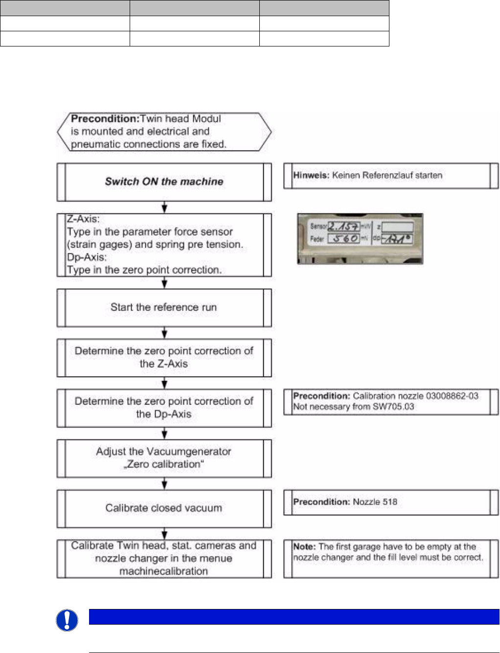
NOTICE
These steps are necessary during the first initial setup or a replacement of the TwinHead
module. The detailed description can be found on the following pages.
TwinHead
Parameter and Calibrations Settings
Student Guide SIPLACE X-Serie and X4I SW70x (AL2) 338
Procedur e
9.4.2.2 Procedure
Entering Parameters
Entering Parameters
Determining the Z Axis Zero Point Correction
Determining the Z Axis Zero Point Correction
After performing a head exchange or service work to the
TwinHead, the following settings are required for
successful calibration of the TwinHead.
1. Entering Parameters
2. Calibrate Z zero point
3. Calibrate Dp zero point
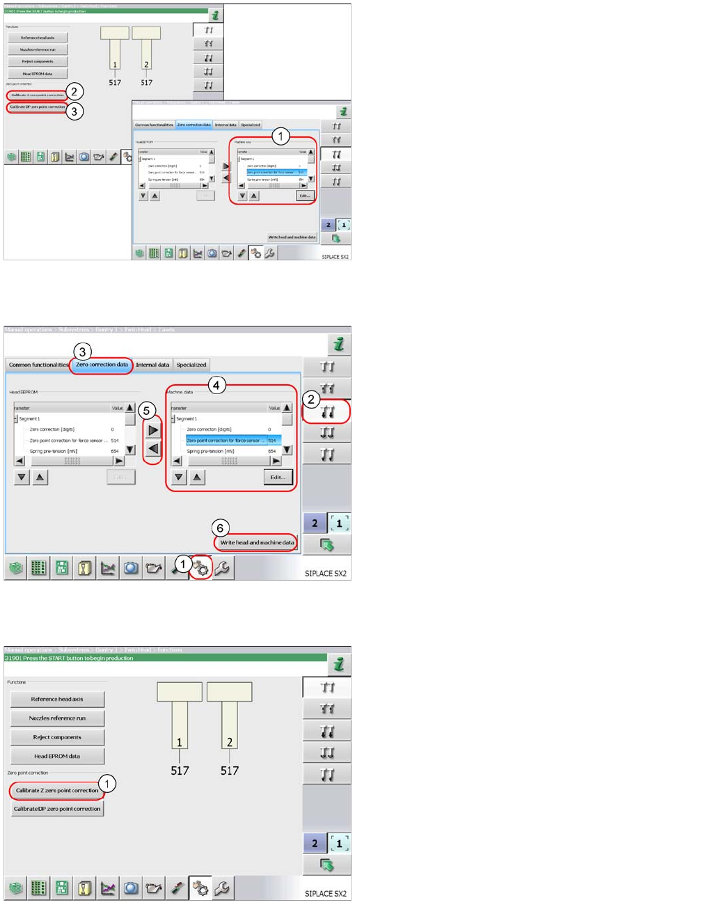
► Log in as service (customer).
► Select Sensors and Functions (1).
► Select the Z axis (2).
► Switch over to the Zero correction data tab (3).
► Mark the parameters at Machine data (4) and
select Edit.
Enter the values for both segments 1 and 2.
Apply the values to the head EEPROM with the arrow
buttons (5).
► Save the values with the Write head and
machine data button (6).
Perform a complete reference run. The TwinHead is
positioned over the fixed conveyor edge to determine the
Z axis zero point correction value.
► To determine the Z axis zero point correction value,
select the Calibrate Z zero point
correction button (1).
TwinHead
Settings Parameter and Calibrations
339 Student Guide SIPLACE X-Serie and X4I SW70x (AL2)
Determining the DP Axis Zero Point C orrection
Determining the DP Axis Zero Point Correction
You need the calibration nozzle [03008862-xx] to check the DP axis zero point correction value.
The zero point correction value is determined automatically with the calibration nozzle. However, it is
essential that the deviation of the current zero point correction value does not exceed +/- 5degrees.
If the deviation is more than 5 degrees, an error message will appear during automatic calibration. In this
case, you need to first perform the zero point correction calibration manually and then automatically.
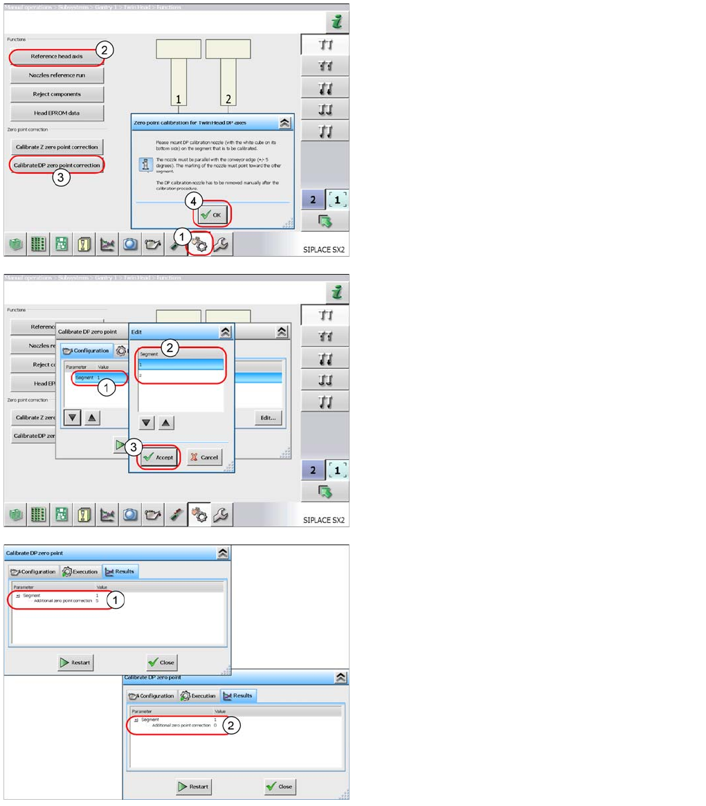
Automaticall y Determining the DP Axis Zero Poi nt Correction
Automatically Determining the DP Axis Zero Point Correction
► Select Sensors and Functions (1).
► Start the Reference head axis (2) function.
► Select Calibrate DP zero point correction
(3).
► Follow the instructions in the window and confirm with
OK (4).
Note: the segment is selected in the next step.
► Once you have attached the calibration tool to
segment 1, select the START button to begin
automatic calibration.
The following applies for segment 2:
► Mark the line with Segment 1 (1) and select the
Edit button.
► In the next window, select segment 2 (2). Confirm the
settings with Accept (3) and start the automatic
calibration.
If the calibration is successful, a value will be shown in
the "Additional zero point correction" line (1).
This will be added to the existing value.
► Repeat the measurement until the Additional
zero point correction has a value of zero (2).
► Close the window. The value will be automatically
saved.