00194614-08 Trainingsdoku. SG X-Serie_X4i SW70x (AL2)_EN.pdf - 第349页
Component Handling Changeover Table Ch angeover Table with One Hand Operation - Func tion 349 Student Guide SIPLACE X-Serie and X4I SW70x (AL2) Dummy Feeder on the X 4I 10.1.2.1 Dummy Feeder on the X4I Changeover Table w…
Component Handling
Structure of the Changeover Table (X- Table) Changeover Table
Student Guide SIPLACE X-Serie and X4I SW70x (AL2) 348
Technical Data (X Table):
Technical Data (X Table):
Structure of the Changeover Table (X- Table)
10.1.2 Structure of the Changeover Table (X- Table)
NOTICE
The SIPLACE X4I machine only supports C&P20A heads, X tables and the feeder types 8, 12
and 16 mm.
Feeder capacity 148 tracks width 8mm, 8mm X feeders
74 tracks width 12mm, 12mm X feeders
60 tracks width 16mm, 16mm X feeders tracks width mm.
Feeder locations: 4 changeover tables with integrated waste tape bins
40 locations, each with 8mm X feeders per component trolley at locations 1
and 3
34 locations, each with 8 mm X feeders per component trolley at locations 2
and 4
Feeder types Tape
Interface to the machine Automatic connection to machine during docking (no connection of cables
needed)
Power supply
CAN bus connection
Closing the safety loop
Compressed air connection
Changeover table
heights:
Based on the conveyor height
830 mm ± 15 mm (standard)
900 mm ± 15 mm (SMEMA)
930 mm ± 15 mm (SMEMA)
950 mm ± 15 mm (SMEMA)
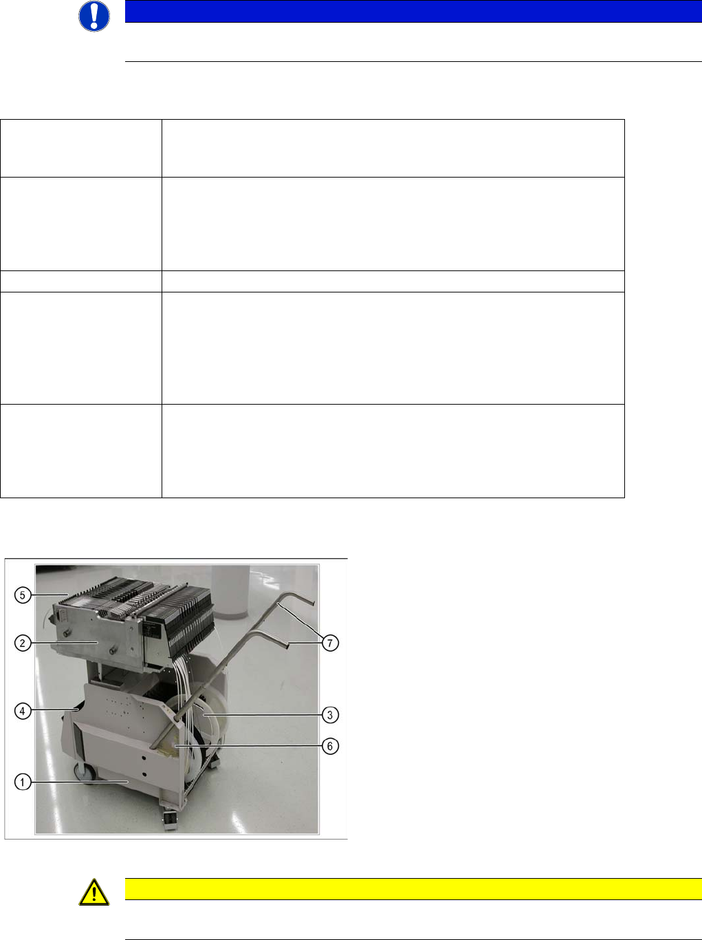
COT (X- table) - side view
Legend
1. Moveable base
2. Changeover table
3. Tape reels container
4. Tape waste bin
5. Interface power supply, communication, safety loop
6. Sticker with an ID number as alphanumeric
characters and as a barcode
7. Handles (can be individually swiveled for model 2)
▪ One pocket can be attached to the side of the
component trolley, for setup list printouts.
CAUTION
Unused locations are to be fitted with dummy feeders to ensure that unauthorized persons do
not reach into the machine.
Component Handling
Changeover Table Changeover Table with One Hand Operation - Function
349 Student Guide SIPLACE X-Serie and X4I SW70x (AL2)
Dummy Feeder on the X4I
10.1.2.1 Dummy Feeder on the X4I
Changeover Table with One Hand Operation - Function
10.1.3 Changeover Table with One Hand Operation - Function
Docking
10.1.3.1 Docking
The docking process can only be performed when the machine is on, compressed air is supplied to the
machine and the safety covers are closed.
To dock the changeover table, push the table as far as possible up to the feed device and press the
button on the machine. On the left and right from the empty tape duct are two centering pins to center
the COT for the final correct pick up position.
The feeder contact plate is raised by two pneumatic cylinders and cam disks while, at the same time, the
entire changeover table is pulled into the machine.
Undocking
10.1.3.2 Undocking
To undock, make sure the compressed air is switched on and the protective cover is open (control
system off) and then press the button on the machine frame. The changeover table is released by the
feed device and is pushed out and lowered by two additional pneumatic cylinders, fixed to the left and
right of the empty tape duct. The COT electrical and pneumatic supply will be automatically disconnected
from the machine. When you press the button on X tables, the system first logs off all feeders in the
software. When machine is OFF:
When the machine is switched off or if there is no compressed air supply, the changeover table can be
easily pulled out of the machine by taking hold of the handles.
CAUTION
The 6 inner tracks can not be reached at locations 2 and 4 of the X4I. A dummy feeder is
therefore automatically inserted here. This also contains the position fiducial for calibration of
the tables.
Component Handling
Changeover Table with One Hand Operation - Function Changeover Table
Student Guide SIPLACE X-Serie and X4I SW70x (AL2) 350
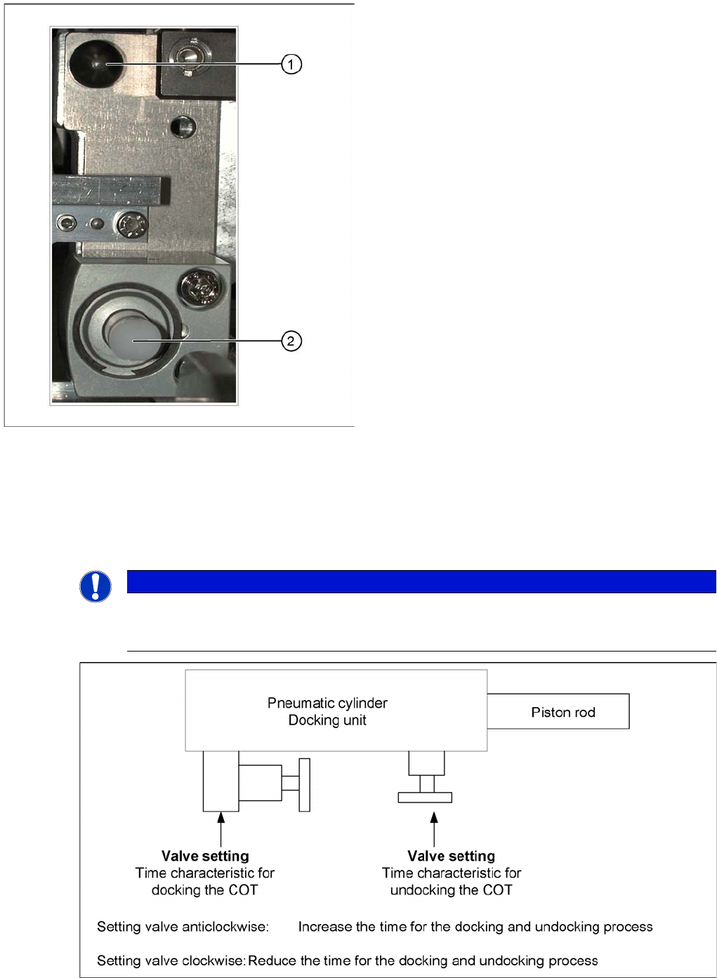
Setting the Pneumatic Cylinder
10.1.3.3 Setting the Pneumatic Cylinder
The movement of the cam disks at the docking unit can be individually set at the valves of the two
cylinders.
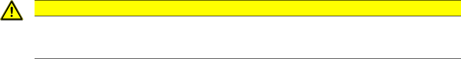
Setting the pneumatic cylinders at the docking unit
Centering pin and pneumatic cylinder at the left and right
of the COT.
Legend
1. Centering Pin for the table plate
2. Cylinder pushing out the COT at undocking
NOTICE
When setting the pneumatic cylinders, make sure that the component trolley is pulled into the
docking unit parallel. The docking and undocking process of the changeover table should be
set to approx. 2 seconds.