00194614-08 Trainingsdoku. SG X-Serie_X4i SW70x (AL2)_EN.pdf - 第351页
Component Handling Changeover Table Ch angeover Table with One Hand Operation - Func tion 351 Student Guide SIPLACE X-Serie and X4I SW70x (AL2) Position ing the D ocking Unit in t he Machine 10.1.3.4 Positioning the Dock…
Component Handling
Changeover Table with One Hand Operation - Function Changeover Table
Student Guide SIPLACE X-Serie and X4I SW70x (AL2) 350
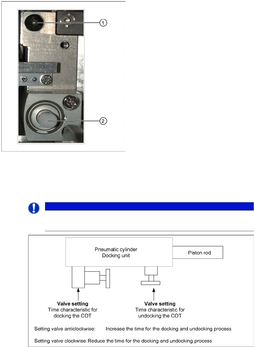
Setting the Pneumatic Cylinder
10.1.3.3 Setting the Pneumatic Cylinder
The movement of the cam disks at the docking unit can be individually set at the valves of the two
cylinders.
Setting the pneumatic cylinders at the docking unit
Centering pin and pneumatic cylinder at the left and right
of the COT.
Legend
1. Centering Pin for the table plate
2. Cylinder pushing out the COT at undocking
NOTICE
When setting the pneumatic cylinders, make sure that the component trolley is pulled into the
docking unit parallel. The docking and undocking process of the changeover table should be
set to approx. 2 seconds.
Component Handling
Changeover Table Changeover Table with One Hand Operation - Function
351 Student Guide SIPLACE X-Serie and X4I SW70x (AL2)
Position ing the D ocking Unit in t he Machine
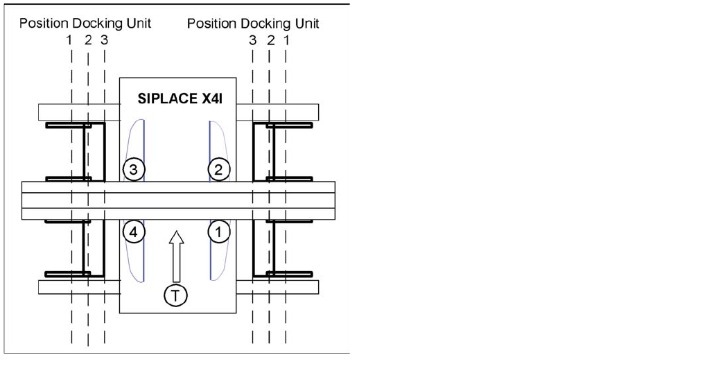
10.1.3.4 Positioning the Docking Unit in the Machine
Positioning the docking unit
SIPLACE X4I
1. Gantry 1
2. Gantry 2
3. Gantry 3
4. Gantry 4
T = transport direction
The docking units can be installed at three different
positions in the machine for each location. The position of
the docking unit depends on the machine type and the
head configuration. Gantries 2 and 4 have been rotated
in the SIPLACE X4I machine. This means that the
docking units at all four locations are mounted in position
3. This creates short travel ranges between the feeders
and the board.
Component Handling
Changeover Table with One Hand Operation - Function Changeover Table
Student Guide SIPLACE X-Serie and X4I SW70x (AL2) 352
Fitting the Docking Unit
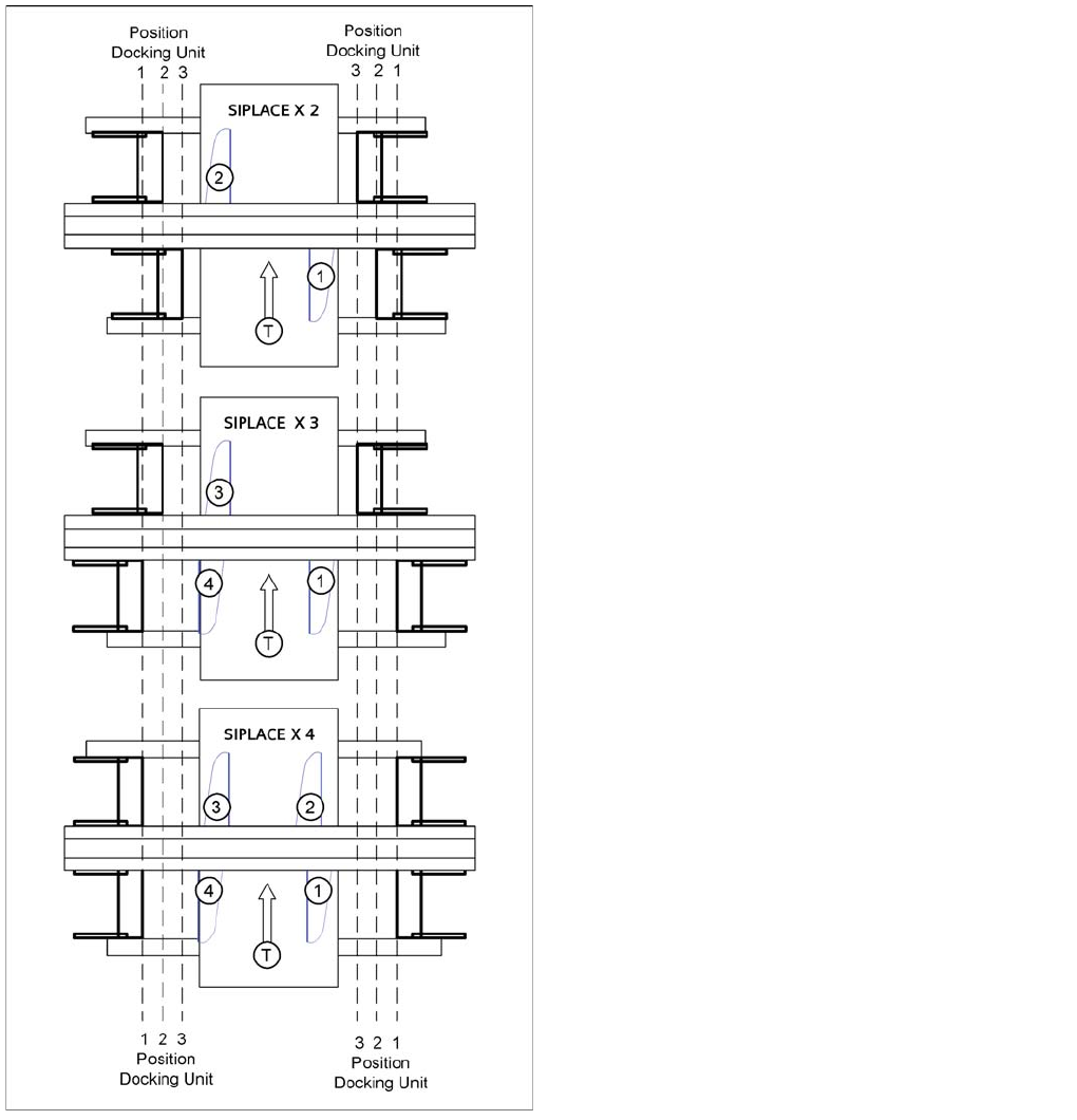
10.1.3.5 Fitting the Docking Unit
To guarantee the precise fit of the table feed device for accurate pickup of small components, the
docking unit on the inside of the machine is fixed with a special fitting screw. When fitting the docking
unit for the changeover table, make sure that this screw is fixed first, before the other screws.
SIPLACE X2, X3 and X4
1. = Gantry 1
2. Gantry 2
3. Gantry 3
4. Gantry 4
T = transport direction
The docking unit of the MTC2 is always installed in
position 3 (see diagram).