00194614-08 Trainingsdoku. SG X-Serie_X4i SW70x (AL2)_EN.pdf - 第36页
Operational Safety Switches and Buttons on the Placement Machine Safety Features Student Guide SIPLACE X-Serie and X4I SW70x (AL2) 36 Safety Feature s 2.4 Safety Features Switches a nd Buttons on the Pl acement Mac hine …
Operational Safety
Safety Instructions for Operating the Machine Safety Instructions for Moving the Component Trolley
35 Student Guide SIPLACE X-Serie and X4I SW70x (AL2)
Safety Instruc tions for Man ual Movemen t of Z Axis on T win Head
2.3.2.1 Safety Instructions for Manual Movement of Z Axis on Twin Head
Safety Ins tructions for Twin Head V ision Modu les
2.3.2.2 Safety Instructions for Twin Head Vision Modules
Safety In structions for M oving the Componen t Trolley
2.3.3 Safety Instructions for Moving the Component Trolley
► Always hold the handles with both hands when you want to move the component trolley.
► Remember that a component trolley with the full complement of feeder modules can tip over
sideways or forward on gradients of 20 or more.
► Make sure that the surface on which the trolley is moved has a significantly smaller gradient.
► Be careful not to collide with obstacles. The trolley could tip forward if it is traveling fast enough.
DANGER
DANGER OF CRUSHING ON Twin HEAD!
Never move the Z axis downwards by holding on to the retract unit bumper. The strong spring
tension of the cylinder moves the bumper back very quickly and could injure your fingers. The
same warning applies to the inside of the Twin head, when the piston rod moves back to its
original position.
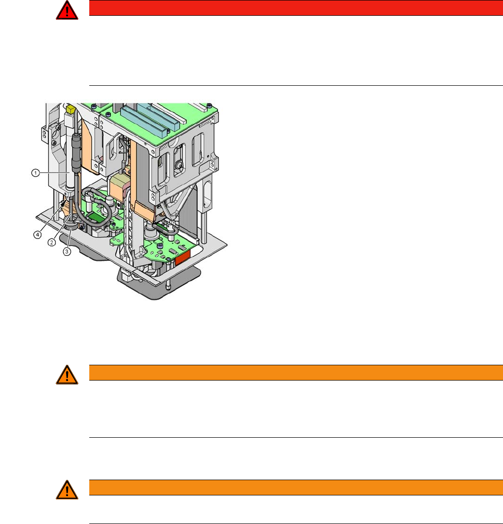
Risk of crushing by retract unit on Twin head
Legend
1. Retract unit, compressed air cylinder
2. Piston rod
3. Retract unit bumper
4. Risk of crushing/trapping fingers
WARNING
Risk of head crash!
When changing the placement head from a Twin head to a C&P, you need to dismantle the fine
pitch and Flipchip Vision modules on the Twin head, otherwise the C&P will collide with the
module housings.
WARNING
To prevent accidents, ALWAYS follow the rules listed below when you move the component
trolley.
Operational Safety
Switches and Buttons on the Placement Machine Safety Features
Student Guide SIPLACE X-Serie and X4I SW70x (AL2) 36
Safety Feature s
2.4 Safety Features
Switches and Buttons on the Placement Machine
2.4.1 Switches and Buttons on the Placement Machine
Position of Switc hes and Buttons on the Pla cement Machine
2.4.1.1 Position of Switches and Buttons on the Placement Machine
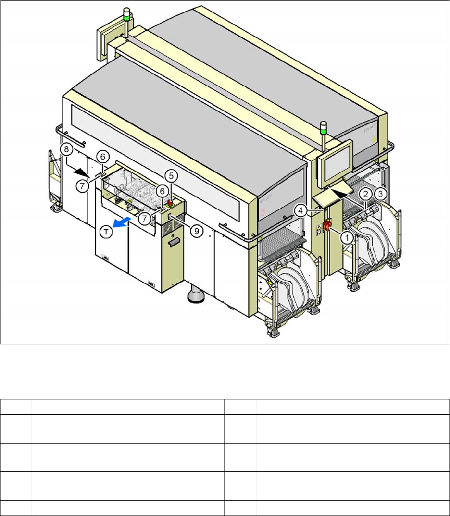
Position of switches and buttons - View of the PCB output side
Legend
1 Main switch 6 Start button (white) on the output side
2 Stop button (black) on the operator panel
on the power supply side
7 Stop button (white) on the output side
3 Start button (white) on the operator panel
on the power supply side
8 Button (black) for docking and undocking
the component trolley, location 2
4 Component counter on the operator panel
on the power supply side
9 Button (black) for docking and undocking
the component trolley, location 3
5 Emergency stop button on the output side T PCB transport direction
Operational Safety
Safety Features Switches and Buttons on the Placement Machine
37 Student Guide SIPLACE X-Serie and X4I SW70x (AL2)
Position of p rotective switches on the placement ma chine
2.4.1.2 Position of protective switches on the placement machine
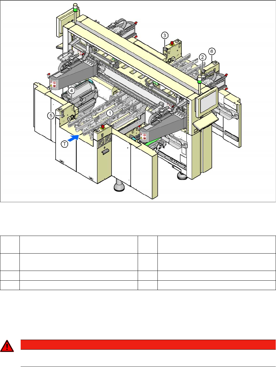
Position of protective switches on the placement machine
Legend
Function Description
2.4.1.3 Function Description
Main power switch in the OFF position
The main power switch disconnects the three phases L1, L2, and L3 from the power supply.
▪ Cable connection terminals L1, L2, and L3 of the Q1 main power switch
▪ Z1 line filter
▪ Service socket X102
▪ F1 automatic circuit breaker for the service socket
1 Protective cover switch, location 1 5 Protective switch for the cover flap on the
PCB conveyor input side
2 Protective cover switch, location 2 6 Protective switch for the cover flap on the
PCB conveyor output side
3 Protective cover switch, location 3 T PCB transport direction
4 Protective cover switch, location 4
DANGER
The following components still carry potentially lethal voltages even if the main power switch is
switched off: