00194614-08 Trainingsdoku. SG X-Serie_X4i SW70x (AL2)_EN.pdf - 第382页
Modular Conveyor Conveyor Control TS P 301 Function Description Student Guide SIPLACE X-Serie and X4I SW70x (AL2) 382 ▪ Downloading the firmware via SITEST ▪ Setting th e conveyor paramet ers (convey or speed ) ▪ Synchro…

Modular Conveyor
Function Description "Long Board" Option
381 Student Guide SIPLACE X-Serie and X4I SW70x (AL2)
"Long B oard" Opti on
11.1.7 "Long Board" Option
The long boards have to be clamped twice per placement area so that each head type (C&P and Twin
head) can place components over the whole board.
The hardware is mounted on the fixed conveyor side.
▪ Mechanical stopper
▪ Programmable ultrasound sensor
This is mounted at one position on the fixed conveyor side of the intermediate and output conveyors.
The ultra sonic sensor is programmed for PCB recognition by placing a PCB above the sensor and
pressing the programming switch for 3 sec.
With this option the standard conveyor light barriers and lasers remain active!
"Alignment Pin" Option
11.1.8 "Alignment Pin" Option
This option is for unfavorable length/width relationship, for cut outs at the leading edge at a PCB board
or for wide and short boards. Mechanical stopper pins are mounted on the flexible conveyor side and on
the lifting table. If the jumper set for this option on the transport interface, The clamping height is learnt
with the first board, so that the pins reach the height of the board. The laser recognize the PCB board
and the conveyor stops after a defined time and the clamping is completed. The clearance under the
PCB board is reduced to 25mm.
"Combined PCB" Option
11.1.9 "Combined PCB" Option
Combined PCB enables you to transport two different boards (top, bottom) into the placement area at
the same time and to place them at the same time. This reduces the transportation times. To make this
option possible, you require an upstream shuttle which collects the boards and a downstream shuttle
which then distributes the boards onto the conveyor lanes.
I-Placem ent Optio n
11.1.10 I-Placement Option
In this option for dual conveyors, the two outer conveyor sides are defined as fixed sides. The two inner
conveyor sides remain flexible and can be adjusted to suit the board widths. This creates shorter travel
ranges between pickup and placement in the SIPLACE X4I machine. In addition, both gantries can pick
up and place independently of one another in the same placement area. Each gantry processes one
board on one lane, independently of the other gantry in this placement area.
Firmware Control Tasks (Embedded Software)
11.1.11 Firmware Control Tasks (Embedded Software)
▪ Transporting, clamping, temporarily storing the PCBs, positioning the PCB using a laser light barrier,
mechanical stopper for long PCBs as an option
▪ Single functions for controlling the conveyor
▪ Adjusting the conveyor width
▪ Addressing the inputs/outputs
NOTICE
To avoid board vibration during placement, use the black PCB supports (94 mm).
NOTICE
X4I
This option is not available for the X4I.
NOTICE
X4I
This option is not available for the X4I.
Modular Conveyor
Conveyor Control TSP 301 Function Description
Student Guide SIPLACE X-Serie and X4I SW70x (AL2) 382
▪ Downloading the firmware via SITEST
▪ Setting the conveyor parameters (conveyor speed)
▪ Synchronous transport mode
Conveyor Control TSP 301
11.1.12 Conveyor Control TSP 301
The conveyor control TSP 301 supports the following options:
▪ Left conveyor side fixed (default: right conveyor side fixed)
▪ "Long PCB" option
▪ PCB Alignment pin
▪ Ceramic substrate centering
▪ Vacuum tooling
▪ PCB barcode
▪ SMEMA interface, SIEMENS (option)
▪ Combined PCB
▪I-Placement
Structure
11.1.13 Structure
Structure of the single conveyor
11.1.13.1 Structure of the single conveyor
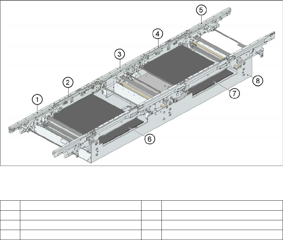
PCB transport - single conveyor
Legend
In SIPLACE X and D3/D4 machines, the single conveyor system consists of an input conveyor, two
placement areas, the intermediate conveyor and the output conveyor. The conveyor has an automatic
width adjustment unit and a lifting table for clamping the PCB.
1 Input belt 5 Output belt
2 Placement area 1 6 Lifting table placement area 1
3 Intermediate belt 7 Lifting table placement area 2
4 Placement area 2 8 Assembly tub
Modular Conveyor
Function Description Structure
383 Student Guide SIPLACE X-Serie and X4I SW70x (AL2)
Structure of the Dual Conveyor
11.1.13.2 Structure of the Dual Conveyor
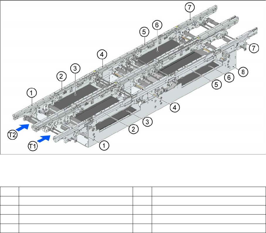
PCB transport - dual conveyor
Legend
The dual conveyor has two conveyor tracks. Depending on the placement mode, line concept and board
size, either the left, right or two outer conveyor sides can be selected as fixed sides.
1 Input belt 6 Lifting table placement area 2
2 Placement area 1 7 Output belt
3 Lifting table placement area 1 8 Assembly tub
4 Intermediate belt T1 Conveyor track 1
5 Placement area 2 T2 Conveyor track 2