00194614-08 Trainingsdoku. SG X-Serie_X4i SW70x (AL2)_EN.pdf - 第383页
Modular Conveyor Function Description Structure 383 Student Guide SIPLACE X-Serie and X4I SW70x (AL2) Structure o f the Dual Conveyor 11.1.13.2 Structure of the Dual Conveyor PCB transport - dual conveyor Legend The dual…
Modular Conveyor
Conveyor Control TSP 301 Function Description
Student Guide SIPLACE X-Serie and X4I SW70x (AL2) 382
▪ Downloading the firmware via SITEST
▪ Setting the conveyor parameters (conveyor speed)
▪ Synchronous transport mode
Conveyor Control TSP 301
11.1.12 Conveyor Control TSP 301
The conveyor control TSP 301 supports the following options:
▪ Left conveyor side fixed (default: right conveyor side fixed)
▪ "Long PCB" option
▪ PCB Alignment pin
▪ Ceramic substrate centering
▪ Vacuum tooling
▪ PCB barcode
▪ SMEMA interface, SIEMENS (option)
▪ Combined PCB
▪I-Placement
Structure
11.1.13 Structure
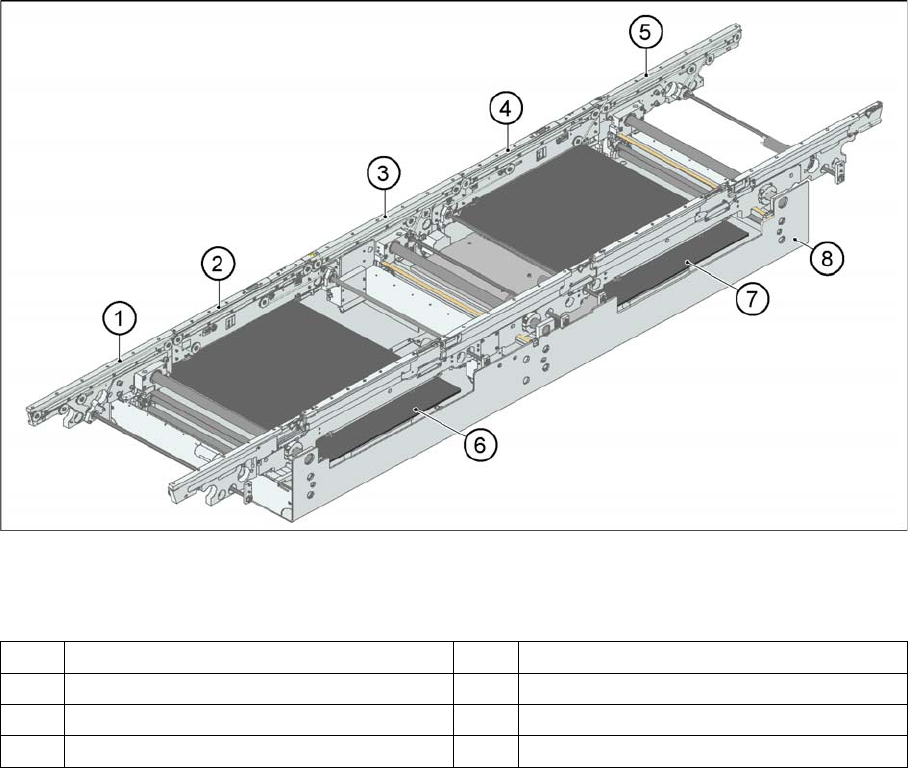
Structure of the single conveyor
11.1.13.1 Structure of the single conveyor
PCB transport - single conveyor
Legend
In SIPLACE X and D3/D4 machines, the single conveyor system consists of an input conveyor, two
placement areas, the intermediate conveyor and the output conveyor. The conveyor has an automatic
width adjustment unit and a lifting table for clamping the PCB.
1 Input belt 5 Output belt
2 Placement area 1 6 Lifting table placement area 1
3 Intermediate belt 7 Lifting table placement area 2
4 Placement area 2 8 Assembly tub
Modular Conveyor
Function Description Structure
383 Student Guide SIPLACE X-Serie and X4I SW70x (AL2)
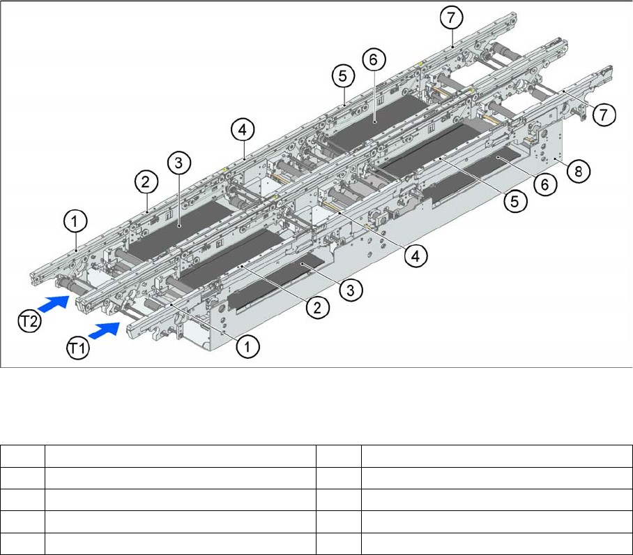
Structure of the Dual Conveyor
11.1.13.2 Structure of the Dual Conveyor
PCB transport - dual conveyor
Legend
The dual conveyor has two conveyor tracks. Depending on the placement mode, line concept and board
size, either the left, right or two outer conveyor sides can be selected as fixed sides.
1 Input belt 6 Lifting table placement area 2
2 Placement area 1 7 Output belt
3 Lifting table placement area 1 8 Assembly tub
4 Intermediate belt T1 Conveyor track 1
5 Placement area 2 T2 Conveyor track 2
Modular Conveyor
Structure Function Description
Student Guide SIPLACE X-Serie and X4I SW70x (AL2) 384
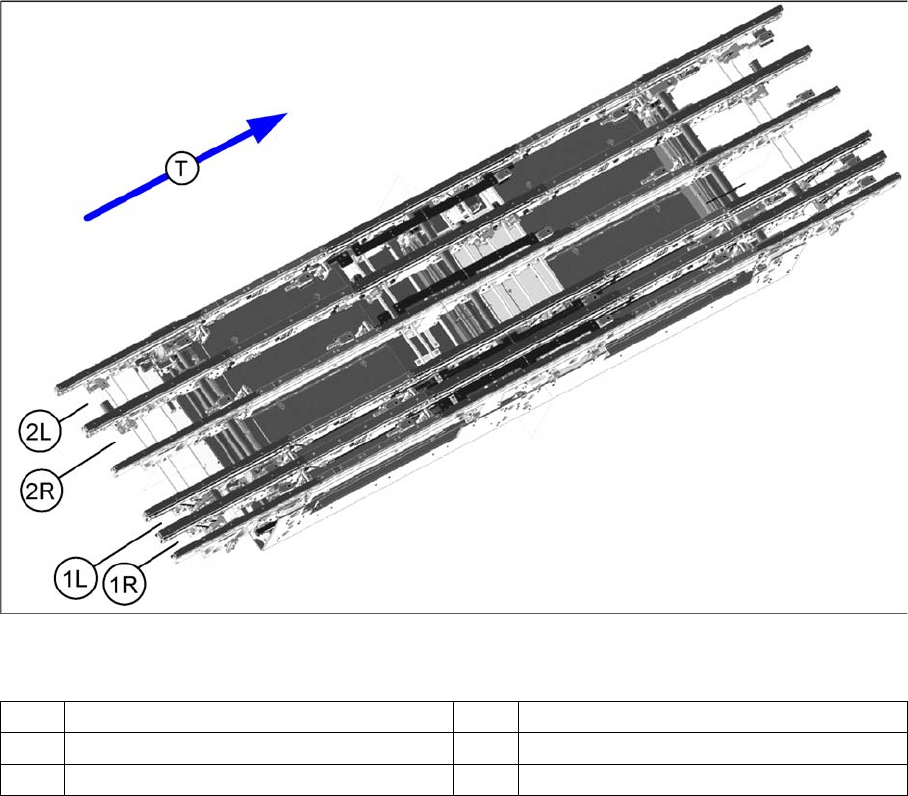
Structur e of Qua d Lane Co nveyor
11.1.13.3 Structure of Quad Lane Conveyor
Legend
The quad lane conveyor has 4 lanes. Conveyor lane 1 is divided into lanes 1L and 1R while conveyor
lane 2 is divided into lanes 2L and 2R.
This conveyor option allows you to produce a complete product with top and bottom sides on the same
conveyor lane. At the same time, another complete product can be produced on the second main lane.
Differences Be tween the X Serie s and X4I Conv eyors With SW70 x
11.1.13.4 Differences Between the X Series and X4I Conveyors With SW70x
▪ Each conveyor side has a fiducial for calibration of the fixed PCB reference corner (from SW70x).
▪ The conveyor and stop position (laser light barrier) in PA1 have been moved 70 mm in the direction
of the input conveyor (max. board length 380 mm).
▪ The length of the bumper under the lifting table plate has been changed from 20 mm to 35 mm. -->
Reduces the transportation times.
▪ Changed setting values for the lifting table times
▪ Changed conveyor zero point and coordinate system with introduction of SW70x
▪ Station software 70x now makes various conveyor modes possible (right, left, outer – fixed conveyor
side).
▪ Conveyor control with switch setting for X4I
(1R) Conveyor lane 1 right (1L) Conveyor lane 1 left
(2R) Conveyor lane 2 right (2L) Conveyor lane 2 left
(T) Transport direction