00194614-08 Trainingsdoku. SG X-Serie_X4i SW70x (AL2)_EN.pdf - 第389页
Modular Conveyor Technical Data Technical Data - Dual C onveyor 389 Student Guide SIPLACE X-Serie and X4I SW70x (AL2) Technical Da ta - Dual Co nveyor 11.2.2 Technical Data - Dual Conveyor Technical Da ta - Flexible Dual…
Modular Conveyor
Technical Data - Single Conveyor Technical Data
Student Guide SIPLACE X-Serie and X4I SW70x (AL2) 388
Overview of Quad Lane Conveyor
11.1.14.5 Overview of Quad Lane Conveyor
See also
11.3.2 Setting the Fixed Conveyor Edge (from SW701) [ ➙ 391]
Technical Data
11.2 Technical Data
Technical Da ta - Single Co nveyor
11.2.1 Technical Data - Single Conveyor
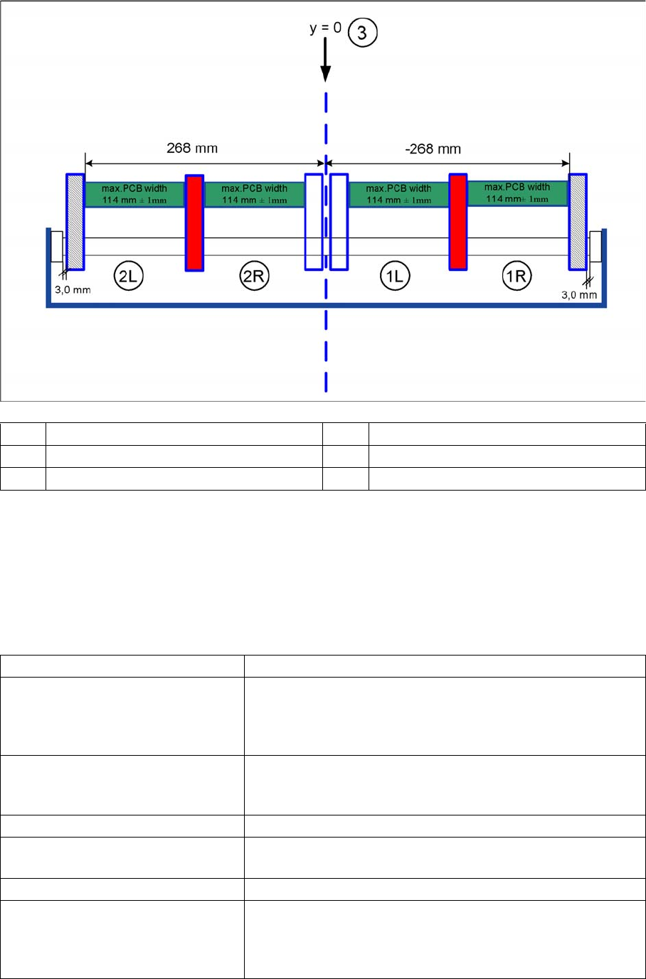
(1L) Lane 1 left (2L) Lane 2 left
(1R) Lane 1 right (2R) Lane 2 right
(3) Machine coordinate system
Fixed conveyor side Right (standard), left (optional)
Max. component height 6 mm for the C&P12
8.5 mm for the C&P6
4 mm for the C&P20A
25 mm for the Twin Head
PCB format (LxW) 50 mm x 50 mm to 450 mm x 508 mm
2" x 2" to 18" x 20"
long board to 610 mm (24"), (option)
PCB thickness 0.3 mm to 4.5 mm
Max. PCB warpage upwards: 6 mm - board thickness
Downwards: 0.3 mm + PCB thickness
Clearance on PCB underside max. 40 mm
PCB transport height 830 mm ±15 mm (standard)
900 mm ±15 mm (option)
930 mm±15 mm (option)
950 mm ±15 mm (option SMEMA)
Modular Conveyor
Technical Data Technical Data - Dual Conveyor
389 Student Guide SIPLACE X-Serie and X4I SW70x (AL2)
Technical Da ta - Dual Co nveyor
11.2.2 Technical Data - Dual Conveyor
Technical Da ta - Flexible Dual Convey or
11.2.3 Technical Data - Flexible Dual Conveyor
Type of interface SMEMA (standard)
SIEMENS (option)
PCB weight 3 kg
Component-free handling edge 3 mm
PCB changeover time 2.5 s
Ink spot recognition possible
Automatic width adjustment possible
Fixed conveyor side Right (standard), left (optional)
Max. component height 6 mm for the C&P12
8.5 mm for the C&P6
4 mm for the C&P20A
25 mm for the Twin Head
PCB format (LxW) 50 mm x 50 mm to 450 mm x 250 mm
2" x 2" to 18" x 8,5"
Long board to 610 mm (24") (option)
PCB thickness 0.3 mm to 4.5 mm
Max. PCB warpage upwards: 6 mm - board thickness
Downwards: 0.3 mm + PCB thickness
Clearance on PCB underside max. 40 mm
PCB transport height 830 mm ± 15 mm (standard)
900 mm ± 15 mm (option)
930 mm± 15 mm (option)
950 mm ± 15 mm (option SMEMA)
Type of interface SMEMA (standard)
SIEMENS (option)
PCB weight 3 kg
Component-free handling edge 3 mm
PCB changeover time 2.5 s
Conveyor mode synchronous or asynchronous
Components on each conveyor same or different
PCB width on each conveyor same or different
Ink spot recognition synchronous: not possible, asynchronous: possible
Automatic width adjustment possible
Feature Single conveyor mode Dual conveyor mode
Max. board size 450 x 450 mm (B x L)
Widths of up to 380 mm are possible
in combination with X3/X2/X4
machines.
250 x 450 mm (B x L)
Widths of up to 450 216 mm are
possible in combination with X3/X2/
X4 machines.
Long board option Possible board length: up to 610 mm Possible board length: up to 610 mm
Modular Conveyor
Setting the Belt Tension Conveyor Settings
Student Guide SIPLACE X-Serie and X4I SW70x (AL2) 390
Conveyor Settings
11.3 Conveyor Settings
Setting t he Belt Ten sion
11.3.1 Setting the Belt Tension
Measuring and setting the belt tension for the width adjustment
CAUTION
Press the EMERGENCY STOP!
Before performing adjustment work you must ensure that the lifting table has been secured
against movement!
NOTICE
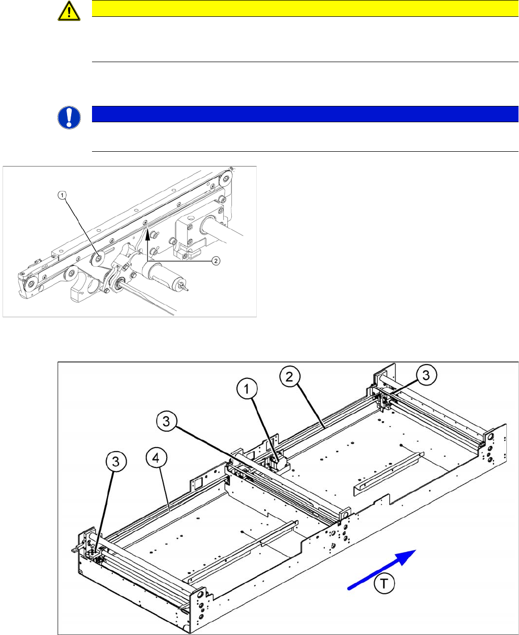
The belt tension is measured at the point where the distance between the two deflection pulleys
is the greatest.
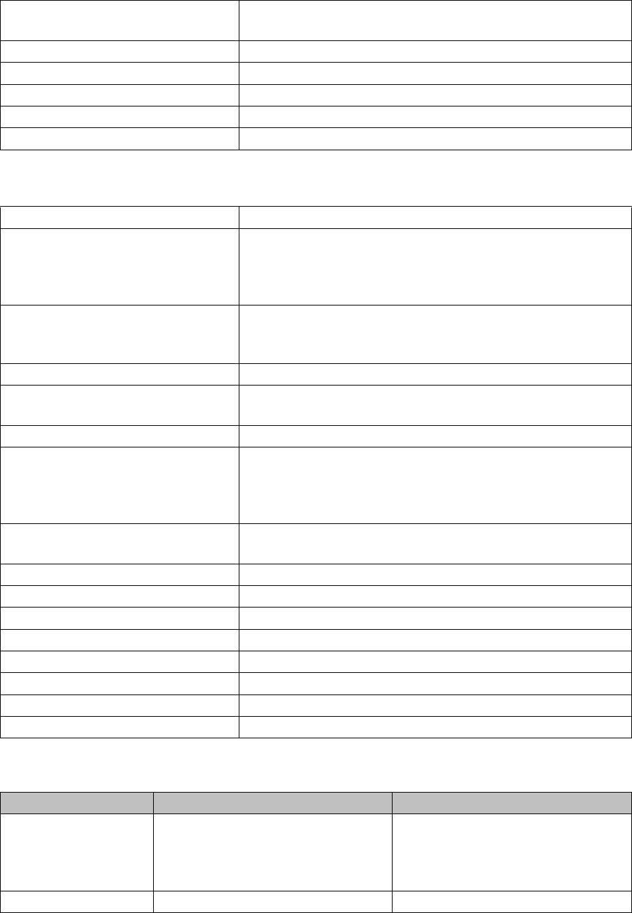
Measuring and setting the tension of the conveyor
toothed belt
Legend
1. Deflection pulley with slot
2. Measuring point of the belt tension measuring device
(strand center )
Each conveyor section contains a deflection pulley that
can be moved. Loosen the fixing screw (1) and move this
deflection pulley in order to set the belt tension for the
associated conveyor belt (2).
The belt tension is measured at the longest point
between two idler pulleys.