00194614-08 Trainingsdoku. SG X-Serie_X4i SW70x (AL2)_EN.pdf - 第39页
Operational Safety Safety Features Position of Pushbutton for Docking and Undocking the Component Trolley 39 Student Guide SIPLACE X-Serie and X4I SW70x (AL2) Position of Pushb utton for Docking and Undocking th e Compon…

Operational Safety
Switches and Buttons on the Placement Machine Safety Features
Student Guide SIPLACE X-Serie and X4I SW70x (AL2) 38
▪ The color of all individual wires, which still carry potentially lethal voltages even if the main power
switch is switched off, is brown.
– Death, serious injury or considerable damage may result if these automatic placement systems
are handled incorrectly.
– Always follow the applicable accident prevention and DIN regulations (particularly DIN EN 60
204, part 1) and the applicable regulations in your own country.
– The safety door to the power supply must ONLY be opened by appropriately qualified and
trained personnel.
EMERGENCY STOP pushbutton, latching, with override protection to EN 418
The emergency stop button is red and latches in the ON position when pressed. When you press the
emergency stop button, the switching contact of the emergency stop circuit opens and the protective
contactor combination (SSK K6) trips. The intermediate circuit voltage (250 VDC) for the gantry axes and
the intermediate circuit voltage (145 VDC) for the star axes is switched off. The servo amplifiers for the
DP and Z axes are still supplied with 40 VDC. The signaling contact of the EMERGENCY STOP button
will open and the message EMERGENCY STOP operated will be shown on the screen. The following
assemblies will be disabled:
▪ PCB conveyor
▪ PCB clamping
▪ Width Adjustment
▪ PCB stopper
▪ Empty tape cutter.
See also
2.4.3.1 Safety Circuit Function [ ➙ 39]
NOTICE
Placement will be interrupted and can then be continued or canceled once the machine is
functional again.
Operational Safety
Safety Features Position of Pushbutton for Docking and Undocking the Component Trolley
39 Student Guide SIPLACE X-Serie and X4I SW70x (AL2)
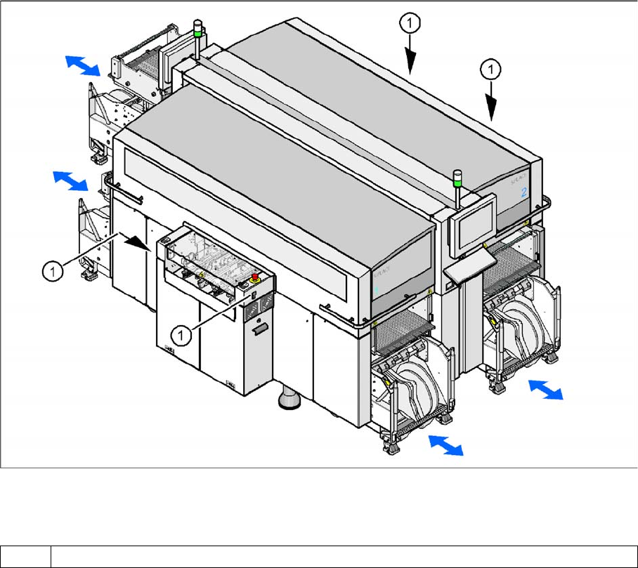
Position of Pushb utton for Docking and Undocking th e Compon ent Trolley
2.4.2 Position of Pushbutton for Docking and Undocking the Component Trolley
Pushbutton for docking and undocking the component trolley
Legend
Safety and Si gnaling Circuit
2.4.3 Safety and Signaling Circuit
Safety Circu it Function
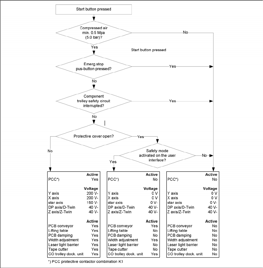
2.4.3.1 Safety Circuit Function
The following conditions must be fulfilled in order to start and operate the placement machine:
▪ All four component trolleys must be docked in and connected.
▪ All protective covers must be closed.
▪ The two cover flaps over the PCB conveyor must be closed.
▪ Both emergency stop buttons must be released.
▪ The cover flaps (option) over the feeder modules must be closed.
▪ The minimum operating pressure must have been reached.
▪ The "software enable" signal must be active. This ensures that the safety circuit is closed.
▪ The power supply must be sending 24 V to the Start buttons and the protective contactor
combination.
▪ If one of the Start buttons is now pressed, the protective contactor combination SSK K6 will switch
and activate the following components:
– 250 VDC intermediate circuit voltage for the servo amplifiers for the gantry axes
– 145 VDC intermediate circuit voltage for the star axes
1 Pushbutton for docking and undocking the component trolley
Operational Safety
Handling ESD Modules ESD Guidelines
Student Guide SIPLACE X-Serie and X4I SW70x (AL2) 40
– The axis unit receives a "servo enable" signal for the servo amplifier
– 48 V for X tables (34 V for S tables, not for X4I) – operating voltage is switched through to
component trolleys
– 24 VDC operating voltage is switched to the used tape cutters.
– The PCB conveyor control receives the enable signal for the PCB clamping, the PCB stopper
and the lifting table control.
The machine is then ready for use.
Safety Loops
2.4.3.2 Safety Loops
Safety Loops
ESD Guidelines
2.5 ESD Guidelines
Handling ESD Mod ules
2.5.1 Handling ESD Modules
Do not touch electronic modules unless it is absolutely essential to do so in order to carry out other work.
If it is necessary, make sure that you do not touch the pins or printed conductors when you pick up flat
modules.