00194614-08 Trainingsdoku. SG X-Serie_X4i SW70x (AL2)_EN.pdf - 第392页
Modular Conveyor Setting the Fixed Conveyor Edge (fr om SW701) Conveyor Settings Student Guide SIPLACE X-Serie and X4I SW70x (AL2) 392 Setting t he Fixed Convey or Edge Setting the Fixed Conveyor Edge The fixed conveyor …
Modular Conveyor
Conveyor Settings Setting the Fixed Conveyor Edge (from SW701)
391 Student Guide SIPLACE X-Serie and X4I SW70x (AL2)
Legend
Belt Tension of PCB Conveyor ( SIPLACE X, X4I)
11.3.1.1 Belt Tension of PCB Conveyor (SIPLACE X, X4I)
Belt tension settings for PCB conveyor (SIPLACE X, X4I, D3)
Setting t he Fixed Convey or Edge (from SW7 01)
11.3.2 Setting the Fixed Conveyor Edge (from SW701)
General Notes
11.3.2.1 General Notes
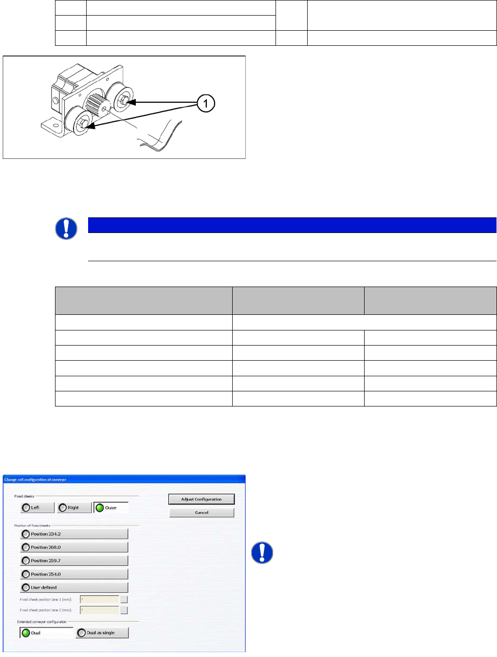
1 Width adjustment stepping motor 4 Toothed drive belt for adjusting the width /
measuring the belt tension
2 Toothed belt for the drive
3 Adjustment unit 1.2 and 3 T Transport direction
Width adjustment motor
The belt is tensioned is set by means of cams on the idler
pulleys. The idler pulleys are located on the left and right
of the motor.
Legend
1. Loosen the cam shaft on the idler pulley and set the
belt tension.
NOTICE
The modular conveyor uses different belt lengths. The different belt tensions between the
conveyor lanes are due to the different arrangement of hexagonal shafts and deflection pulleys.
Belt tension For lane 1
(single and dual conveyor)
For lane 2
(dual conveyor)
Belt tension for the width adjustment 30 Hz +/-2 Hz
Input belt 102 Hz +/- -10 Hz 144 Hz +/- -14 Hz
Placement area 1 66 Hz +/- -7 Hz 71 Hz +/- -7 Hz
Intermediate belt 94 Hz +/- -9 Hz 94 Hz +/- -9 Hz
Placement area 2 66 Hz +/- -7 Hz 71 Hz +/- -7 Hz
Output belt 102 Hz +/- -10 Hz 144 Hz +/- -14 Hz
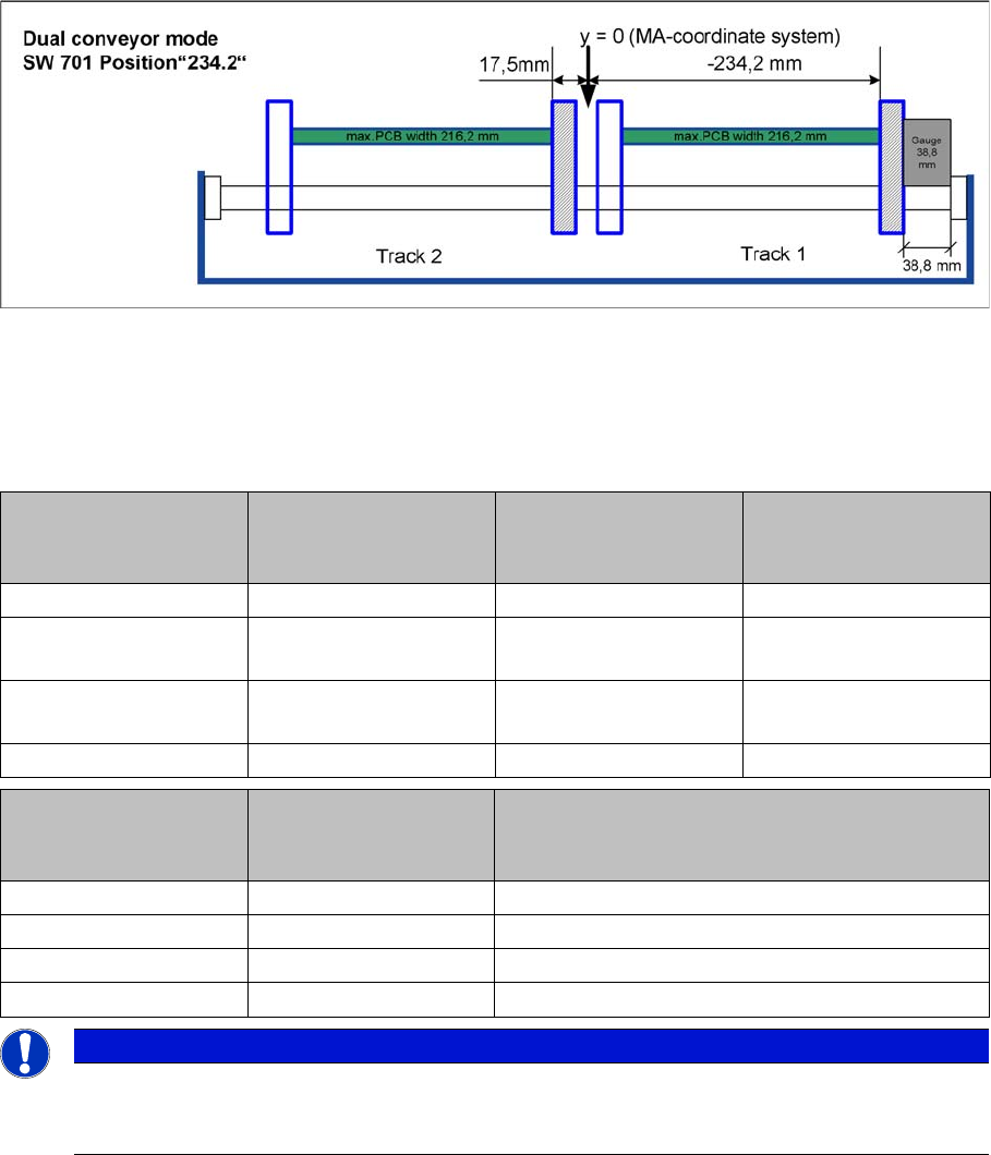
When using dual conveyors in the X4I, the fixed conveyor
edge can be set as required i.e. the left or right side, or
the outer edges of each conveyor for i-placement. The
compatibility to the other machines can be set via
predefined values in the SW (see diagram).
NOTICE! This menu is available from user level
!
Service (customer)
Modular Conveyor
Setting the Fixed Conveyor Edge (from SW701) Conveyor Settings
Student Guide SIPLACE X-Serie and X4I SW70x (AL2) 392
Setting t he Fixed Convey or Edge
Setting the Fixed Conveyor Edge
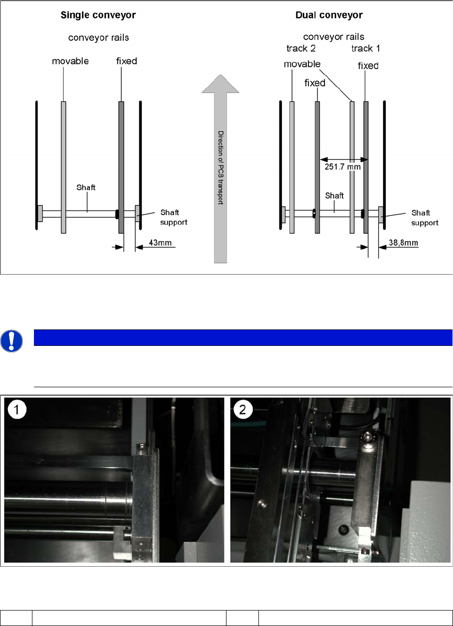
The fixed conveyor edge is always set in the standard mode with right side fixed. You need to set a value
of 38.8 mm between the conveyor base and the fixed conveyor edge, with the help of a gauge.
▪ [03054247-xx] Gauge for fixed conveyor edge DT/ET HS60/D4
▪ [03054248-xx] Gauge for conveyor edge distance DT HS-60/D4
Teach the fixed side with the software and store the value.
Setting the fixed conveyor edge
Values
Measurement is performed between the side flange and the conveyor edge assembly flange.(See also
"X series example")
Machine Single conveyor
Standard width
508 (460) mm
Dual conveyor
Standard width
250 (216) mm
Quad lane
Standard width
114 mm
HF series 19 (43) mm 4.5 (38.8) mm
X series / D3
Until July 2007
19 (43) mm 4.5 (38.8) mm
X series / D3
From July 2007
16 (40) mm 4.5 (38.8) mm 2 mm
X4I 16 (40) mm 4.5 (38.8) mm 2 mm
Machine Single conveyor
Standard width
(460) mm
Dual conveyor
Standard width
(216) mm
HS-60 34,5 mm 30,5 mm
S27 HM 34,5 mm 30,5 mm
D4 34,5 mm 30,5 mm
D1/D2 34,5 mm 30,5 mm
NOTICE
The fixed conveyor side should be adjusted only with the SITEST software and the width
adjustment devices. This ensures that the conveyor edges are in their correct positions
(parallel) i.e. that the conveyor runs straight.
Modular Conveyor
Conveyor Settings Setting the Fixed Conveyor Edge (from SW701)
393 Student Guide SIPLACE X-Serie and X4I SW70x (AL2)
X series example
Setting the "fixed conveyor edge" in SIPLACE X, HF series
Shaft mount (bearing flange)
Legend
▪ After teaching the fixed conveyor edge, you need to recalibrate the PCB reference corner, to prevent
fiducial errors during placement.
NOTICE
Since July 2007 there is a new version of the shaft mount (bearing flange) for X machines with
single conveyors with 15 mm width instead of 12 mm. The setting for the standard single
conveyor therefore changes to 40 mm when this new version is used.
(1) Bearing flange – first version 12 mm (1) Bearing flange – new version 15 mm