00194614-08 Trainingsdoku. SG X-Serie_X4i SW70x (AL2)_EN.pdf - 第40页
Operational Safety Handling ESD Modules ESD Guidelines Student Guide SIPLACE X-Serie and X4I SW70x (AL2) 40 – The axis unit receives a "servo enable" signal for the servo a mplifier – 48 V for X t ables (34 V f…
Operational Safety
Safety Features Position of Pushbutton for Docking and Undocking the Component Trolley
39 Student Guide SIPLACE X-Serie and X4I SW70x (AL2)
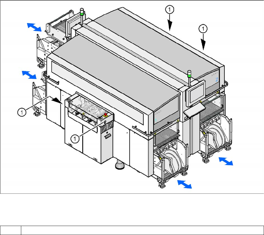
Position of Pushb utton for Docking and Undocking th e Compon ent Trolley
2.4.2 Position of Pushbutton for Docking and Undocking the Component Trolley
Pushbutton for docking and undocking the component trolley
Legend
Safety and Si gnaling Circuit
2.4.3 Safety and Signaling Circuit
Safety Circu it Function
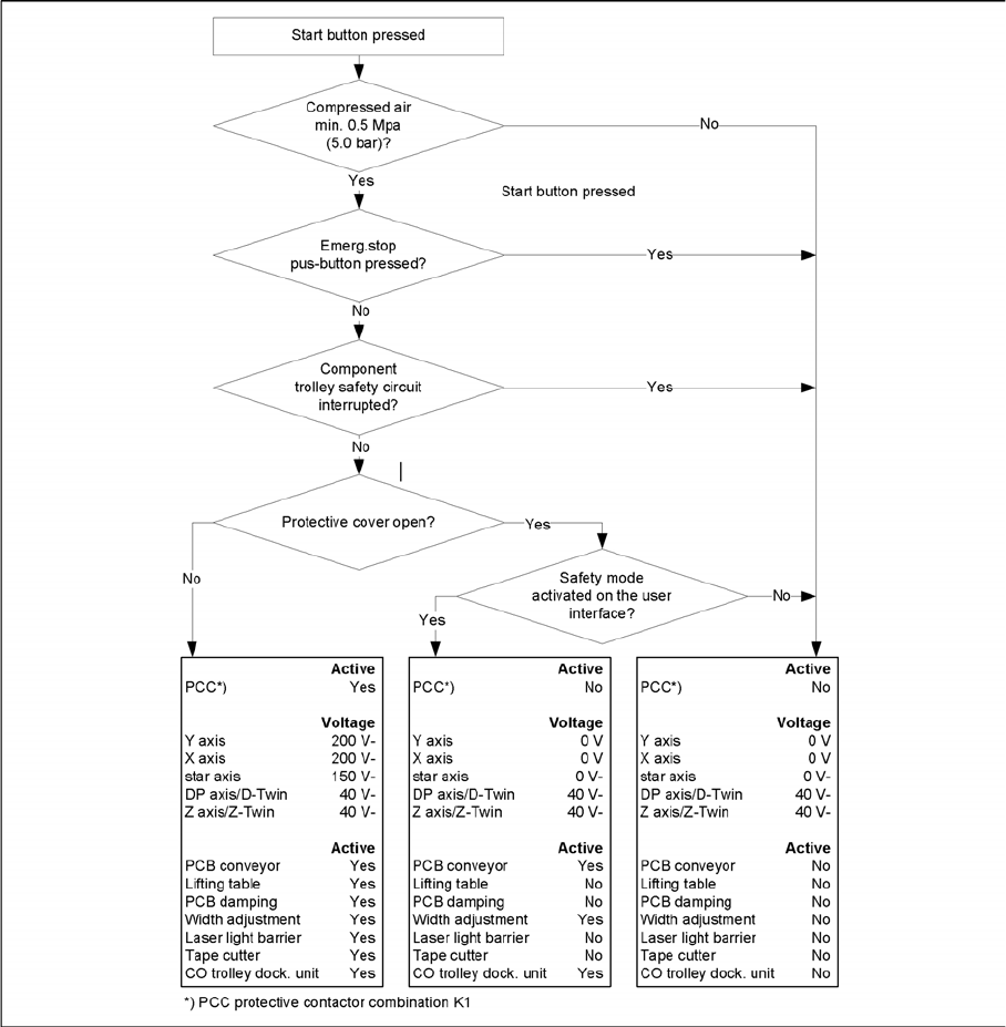
2.4.3.1 Safety Circuit Function
The following conditions must be fulfilled in order to start and operate the placement machine:
▪ All four component trolleys must be docked in and connected.
▪ All protective covers must be closed.
▪ The two cover flaps over the PCB conveyor must be closed.
▪ Both emergency stop buttons must be released.
▪ The cover flaps (option) over the feeder modules must be closed.
▪ The minimum operating pressure must have been reached.
▪ The "software enable" signal must be active. This ensures that the safety circuit is closed.
▪ The power supply must be sending 24 V to the Start buttons and the protective contactor
combination.
▪ If one of the Start buttons is now pressed, the protective contactor combination SSK K6 will switch
and activate the following components:
– 250 VDC intermediate circuit voltage for the servo amplifiers for the gantry axes
– 145 VDC intermediate circuit voltage for the star axes
1 Pushbutton for docking and undocking the component trolley
Operational Safety
Handling ESD Modules ESD Guidelines
Student Guide SIPLACE X-Serie and X4I SW70x (AL2) 40
– The axis unit receives a "servo enable" signal for the servo amplifier
– 48 V for X tables (34 V for S tables, not for X4I) – operating voltage is switched through to
component trolleys
– 24 VDC operating voltage is switched to the used tape cutters.
– The PCB conveyor control receives the enable signal for the PCB clamping, the PCB stopper
and the lifting table control.
The machine is then ready for use.
Safety Loops
2.4.3.2 Safety Loops
Safety Loops
ESD Guidelines
2.5 ESD Guidelines
Handling ESD Mod ules
2.5.1 Handling ESD Modules
Do not touch electronic modules unless it is absolutely essential to do so in order to carry out other work.
If it is necessary, make sure that you do not touch the pins or printed conductors when you pick up flat
modules.
Operational Safety
ESD Guidelines Measurements and Modifications to ESD Modules
41 Student Guide SIPLACE X-Serie and X4I SW70x (AL2)
Do not touch components unless
▪ you are constantly earthed by an ESD wrist strap or
▪ you are wearing ESD shoes or ESD shoe earthing strips on an ESD floor.
Always discharge yourself before you touch an electronic module. To do this, simply touch a conductive
and earthed object immediately before you touch the module (such as unpainted parts of a switch
cabinet, a water pipe, etc.).
Do not allow modules with chargeable and highly insulating materials to touch one another, e.g. plastic
films, insulating table surfaces or items of clothing made from synthetic fibers.
Always place the modules on a conductive surface (table with an ESD coating, conductive ESD foam,
ESD bag or container).
Do not bring modules near visual display units, monitors or televisions. Keep them at least 10 cm away
from the screen.
Measurements and Modifications to ESD Modules
2.5.2 Measurements and Modifications to ESD Modules
Do not take measurements on such modules unless
▪ the measuring device is earthed (e.g. via PE conductors) or
▪ you discharge the measuring head just before taking measurements with a potential-free measuring
device (e.g. by touching an unpainted metal part of the controller casing).
► Always use an earthed soldering iron if you carry out any soldering work.
Dispatching ESD Modules
2.5.3 Dispatching ESD Modules
► Always store modules and components in conductive packaging (e.g. metallized plastic bags or
metal sleeves) and dispatch them in conductive packaging.
► If the packaging is not conductive, place the modules in a conductive envelope before packaging.
Use conductive expanded rubber, ESD bags, domestic aluminum foil or paper, for example. NEVER
use plastic bags or film.
► If the module has integral batteries, ensure that the conductive packaging does not touch or short-
circuit the battery terminals and, if necessary, first cover the terminals with insulating tape or
material.