00194614-08 Trainingsdoku. SG X-Serie_X4i SW70x (AL2)_EN.pdf - 第407页
Modular Conveyor Conveyor Settings Conveyor Control T SP 301 407 Student Guide SIPLACE X-Serie and X4I SW70x (AL2) Conveyor C ontrol TS P 301 wit h Siemens Interfac e 11.3.10.2 Conveyor Control TSP 301 with Siemens Inter…
Modular Conveyor
Conveyor Control TSP 301 Conveyor Settings
Student Guide SIPLACE X-Serie and X4I SW70x (AL2) 406
Conveyor Control TSP 301
11.3.10 Conveyor Control TSP 301
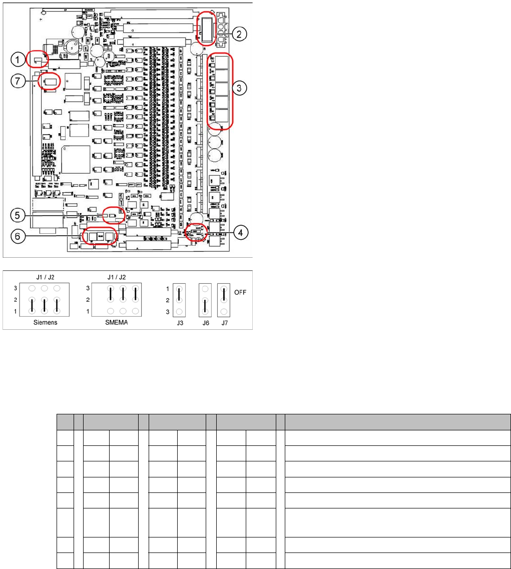
Jumper Settings for TSP 301
11.3.10.1 Jumper Settings for TSP 301
DIL switch S4 at TSP 301
* Switches 1 and 2 set the hardware ID 5 for D4 machines and hardware ID 6 for X4I, X series, HF and
D3.
Legend
1. J7 CAN bus 1 terminating resistor
2. F6 Main Fuse TSP 301
3. F1 - F5 Fuses for the conveyor motors
4. J3 interference loop
5. J6 CAN bus 2 terminating resistor (not used)
6. J2, J1 successor/predecessor station
7. S4 DIL switch
Jumper J1, J2 "downstream/upstream station" at TSP
301
Legend
▪ J1 predecessor station
▪ J2 successor station
▪ J3 interference loop (EMERGENCY STOP on
productivity lift also switches the placement machine
off)
▪ J6 CAN bus 2 terminating resistor (not used)
▪ J7 CAN bus 1 terminating resistor
S X4I D4 X/D3/HF Comments
1* ON ON ON ON
2* OFF ON OFF ON = SIPLACE D4, OFF: SIPLACE X, HF, D3, X4I
3 OFF OFF OFF OFF= clamping sensor is no longer used
4 ON ON OFF OFF ON ON = quad lane, OFF: default conveyor
5 OFF OFF OFF Not in use
6 OFF ON OFF OFF ON OFF: Default conveyor, ON: quad lane (conveyor
edges fixed on outside)
7 OFF OFF OFF Not in use
8 OFF OFF OFF Not in use
Modular Conveyor
Conveyor Settings Conveyor Control TSP 301
407 Student Guide SIPLACE X-Serie and X4I SW70x (AL2)
Conveyor Control TSP 301 with Siemens Interface
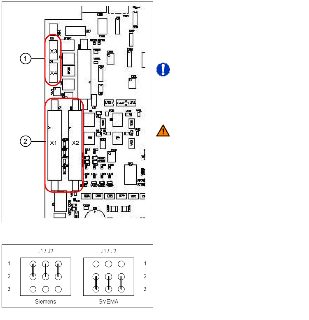
11.3.10.2 Conveyor Control TSP 301 with Siemens Interface
TSP 301 SMEMA --> Siemens
Legend
1. 10-pin plug for SMEMA interface
X3: upstream station
X4: successor station
2. Connection for Siemens interface
X1: upstream station
X2: successor station
NOTICE! Standard / Option
The SMEMA interface is a standard on all X machines
and the Siemens interface is optional.
The Siemens interface is a standard on all D machines
and the SMEMA interface is optional. The SMEMA
interface requires an adapter when used with the D1/2/4.
WARNING! Risk of irreparable damage to the
TSP board!
The 10 pin Locking clip plug of SMEMA connections must
be disconnected from the TSP 301!
Application: no modification.
Following modification are necessary for using the
Siemens interface:
► JumperJ1 / J2: need to be moved (see following
diagram).
► Disconnect the connector X3 and X4 on the TSP 301!
► Connect the Siemens interface cable on the
connector X1 and X2.
Jumper J1 and J2 (Siemens/SMEMA)
Modular Conveyor
Conveyor Control TSP 301 Conveyor Settings
Student Guide SIPLACE X-Serie and X4I SW70x (AL2) 408
LED Display on Conveyor Control TSP 301
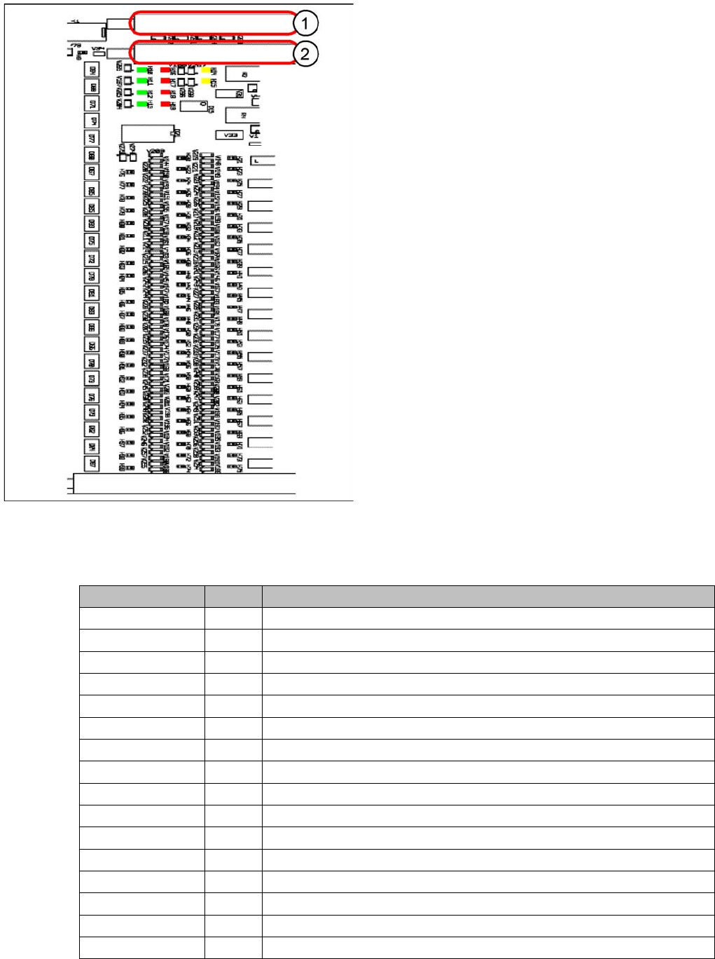
11.3.10.3 LED Display on Conveyor Control TSP 301
Assignme nt Table: LEDs on the TSP 301 Conv eyor Contr ol
11.3.10.4 Assignment Table: LEDs on the TSP 301 Conveyor Control
Conveyor Control TSP 301
Legend
1. PCB-Handling interface previous station track 1 with
diagnosis LED’s PCB-handling
2. PCB-Handling interface following station track 1 with
diagnosis LED’s PCB-handling
The "Siemens board handling interface for the
predecessor station of lane 2 with corresponding LEDs
for board handling" plug and the "board handling
interface for the successor station of lane 2 with
corresponding LEDs for board handling" plug are located
on the extension board (similar layout).
Anzeige /Display I / O LED assignment
H1 / F1-F5 Fuse F1-F5, Power supply 40 V
H2 / F6 Fuse F6 Power supply 24V
H4(ao) Initializing / control error
H5(ao) CAN bus 1, active
H6(ao) Flashing: Program running
H7(ao) CAN bus 2, active (optional)
H9 Out Interference loop
H14 IN Siemens interface for upstream station
H15 IN Siemens interface for downstream station
H20 IN Lifting table, placement area 1: Fork light barrier A
H21 IN Lifting table, placement area 1: Fork light barrier B
H22 IN Lifting table, placement area 2: Fork light barrier A
H23 IN Lifting table, placement area 2: Fork light barrier B
H24 IN Laser light barrier, placement area 1: Receiver
H25 IN Laser light barrier, placement area 2: Receiver
H26 IN Not in use