00194614-08 Trainingsdoku. SG X-Serie_X4i SW70x (AL2)_EN.pdf - 第447页
MTC2 Overview Operational Safety 447 Student Guide SIPLACE X-Serie and X4I SW70x (AL2) The two protective doors are each equipped with a protective do or switch. These ar e looped into the starting circuit of the respe c…
MTC2
Operational Safety Overview
Student Guide SIPLACE X-Serie and X4I SW70x (AL2) 446
Protectiv e Door Switches
Protective Door Switches
Combination circuit breakers
Combination circuit breakers
Safety and Si gnaling Circuit
Safety and Signaling Circuit
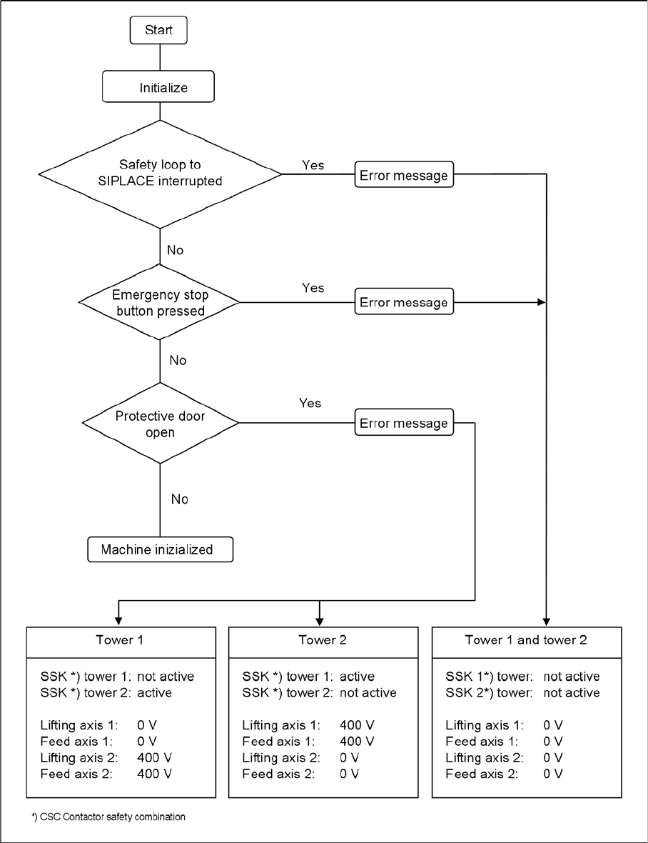
The safety circuit consists of three safety combinations, which work completely independently of each
other. They are used to monitor the following actions:
▪ Actuation of the EMERGENCY STOP button
▪ Opening the protective door of tower 1
▪ Opening the protective door of tower 2
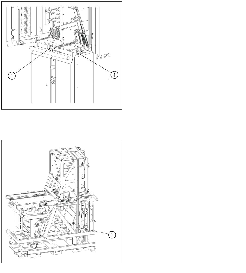
Position of the protective door switches
These switches check whether the two protective doors
are closed. If the doors are closed, the safety contact and
the signaling contact are closed. When one of the doors
is opened, the safety circuit and the signaling circuit are
opened. The corresponding safety combination is
triggered and the tower is powered down. The following
error message appears: “Tower x: Protective door not
closed”.
Legend
1. Protective Door Switches
Position of the combination circuit breakers
The combination circuit breakers are fitted on the rear of
the masterdrive housing. In the event of malfunctions that
are relevant to safety, they are triggered.
Legend
1. Combination circuit breakers
MTC2
Overview Operational Safety
447 Student Guide SIPLACE X-Serie and X4I SW70x (AL2)
The two protective doors are each equipped with a protective door switch. These are looped into the
starting circuit of the respective monitoring device.
If the EMERGENCY STOP button is pressed during operation or one of the two protective doors opens,
the relevant safety combination is tripped and the drives are locked via contactors on the electronics
board.
The signaling circuit for the protective door monitoring system is transmitted to the MTC2 controller by
the relevant safety combinations, via normally open contacts.
MTC2
Operational Safety Construction and mode of operation
Student Guide SIPLACE X-Serie and X4I SW70x (AL2) 448
Safety Loops
Safety Loops
Safety Loops
Construction and mode of operation
13.2 Construction and mode of operation
The MTC2 extends the capacity of a SIPLACE station to supply components by up to 100 JEDEC waffle
pack trays. It has its own controller (C167 controller board) and is integrated into the station computer
software. The setup of the MTC2 is integrated into the line controller software of a system.