00194614-08 Trainingsdoku. SG X-Serie_X4i SW70x (AL2)_EN.pdf - 第449页
MTC2 Construction and mode of operation Lifting and Feeder Motors 449 Student Guide SIPLACE X-Serie and X4I SW70x (AL2) Each of the two MTC2 towers has a lifting axis and a feed axis. Th e lifting axes c an be set up wit…
MTC2
Operational Safety Construction and mode of operation
Student Guide SIPLACE X-Serie and X4I SW70x (AL2) 448
Safety Loops
Safety Loops
Safety Loops
Construction and mode of operation
13.2 Construction and mode of operation
The MTC2 extends the capacity of a SIPLACE station to supply components by up to 100 JEDEC waffle
pack trays. It has its own controller (C167 controller board) and is integrated into the station computer
software. The setup of the MTC2 is integrated into the line controller software of a system.

MTC2
Construction and mode of operation Lifting and Feeder Motors
449 Student Guide SIPLACE X-Serie and X4I SW70x (AL2)
Each of the two MTC2 towers has a lifting axis and a feed axis. The lifting axes can be set up with a large
number of waffle pack trays in cassettes and transport these vertically. The feed axes transport waffle
pack trays which have been set up horizontally to the transfer position to the SIPLACE station.
All drive units comprise Masterdrive drive systems:
▪ The servo motors of the lifting axes each drive a spindle via a dual toothed belt, which transports
vertically the cassettes which have been set up. A holding brake in the motors, which is controlled
by the Masterdrive via optocouplers, prevents the axis from moving when the machine is switched
off. The lifting axes remain under control when a position has been reached. The toothed belts are
duplicated for safety reasons and are monitored using inductive sensors.
▪ The servo motors of the feed axes use a toothed belt and belt gear to move a driver, which then
moves the selected WTC horizontally to the transfer position of the SIPLACE station.
Lifting axis
One revolution of the servo motor is equivalent to 4096 pulses or a lift of 10 mm on the spindle.
Feed axis
One revolution on the servo motor is equivalent to 4096 pulses or 27.78 mm on the linear guide.
Lifting and Feede r Motors
13.2.1 Lifting and Feeder Motors
NOTICE
Same motor types for lifting and feeder motors!
Both lifting axis motors and the two feeder axis motors must be of the same type:
MTC2 version 01 [03011837-01]: Motor type 1 FK6 [00354906-01]
MTC2 version 02 [03011837-02]: Motor type 1 FK7 [03035813-01]
Lifting axis features MTC2 zero series
(Mühlbauer)
MTC2 – version 01
modification 401431:
MTC2 – version 02
modification
401471:
Counterbearing spindle Without With With
Spindle lift P=10 P=10 P=12
Spindle speed 3000 1/min 3000 1/min 2500 1/min
Motor pinion (toothed wheel) 36 teeth 36 teeth 30 teeth
Motor type 1FK6 1FK6 1FK7 or 1FK6
Belt tension 170 ± 5 Hz 200 ± 5 Hz 210 ± 5 Hz
MTC2
Incorporating the MTC in the SIPLACE station Construction and mode of operation
Student Guide SIPLACE X-Serie and X4I SW70x (AL2) 450
Incorpor ating the MTC in the SIP LACE stat ion
13.2.2 Incorporating the MTC in the SIPLACE station
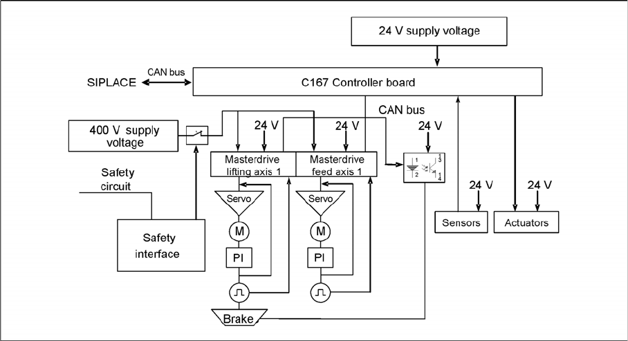
MTC2 interfaces and power supply (shown for tower 1)
CAN Bus
This interface is used for all commands which are sent by the machine controller of the SIPLACE station.
Example: Reference position run and transfer of set-up data.
400 V power supply
The MTC2 is supplied externally with 400 V (USA/Japan: 208/204 V).
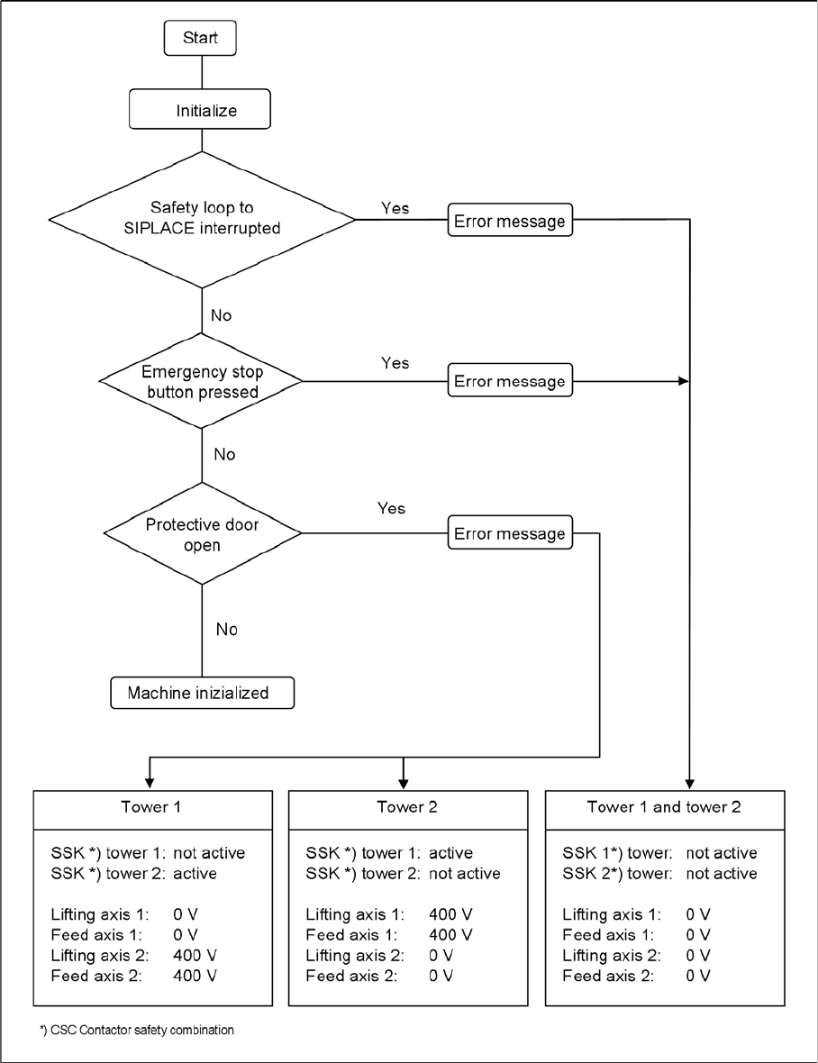
EMERGENCY STOP interface
The MTC2 is incorporated into the safety circuit of the SIPLACE station. This provides feedback in the
form of a protective circuit voltage of 24 V. This protective circuit voltage switches the relevant
combination circuit breaker and thus the 400 V of the inverters for the Masterdrives.
The contactors switch off the servo voltage (400 V) and also immediately switch off the power supply to
the brake.
The signaling contact (make contact) of the EMERGENCY STOP button is connected to the input of the
SIPLACE safety signalling system. The break contact interrupts the 24 V protective circuit voltage of the
SIPLACE machine.
If the EMERGENCY STOP circuit in a machine is interrupted (EMERGENCY STOP button), the master
drives of the MTC2 will trip. Both systems are then not under power.
When one of the two MTC2 protective doors is opened, only the control voltage of the relevant tower
falls.
Reference position run
13.2.3 Reference position run
When the MTC2 is switched on, a reference position run needs to be performed for the servo axes, as
for the SIPLACE station. If the MTC2 remains switched on when the SIPLACE station is switched off and
back on, it will report that it has already been referenced.
During the reference position run, both towers move into their reference positions simultaneously. The
two feed axes are moved first and then the two lifting axes.