00194614-08 Trainingsdoku. SG X-Serie_X4i SW70x (AL2)_EN.pdf - 第47页
Overview SIPLACE X Series Configurations 47 Student Guide SIPLACE X-Serie and X4I SW70x (AL2) SIPLACE X3 with 1 MTC2 - Configu ration 3.1.2.3 SIPLACE X3 with 1 MTC2 - Configuration SIPLACE X3 wi th 2 MTC2 - Co nfiguratio…
Overview
Configurations SIPLACE X Series
Student Guide SIPLACE X-Serie and X4I SW70x (AL2) 46
Configura tions
3.1.2 Configurations
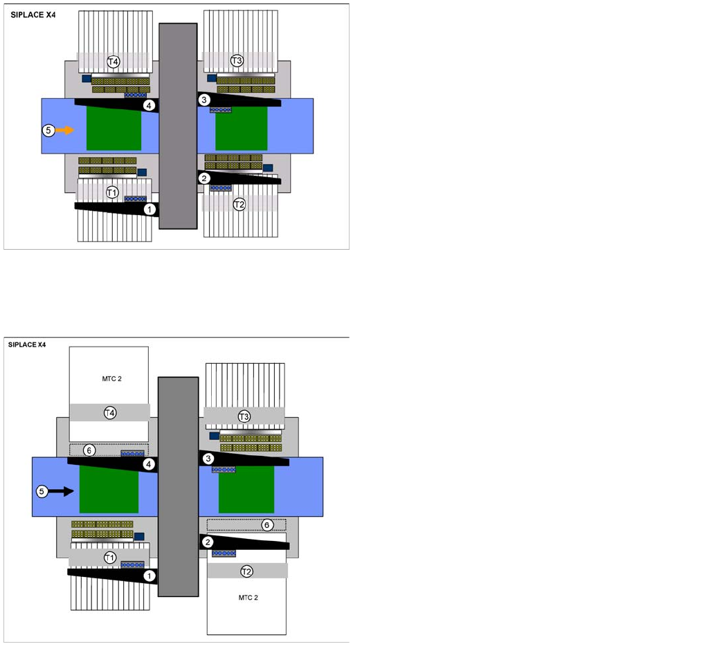
SIPLACE X4 Conf iguration
3.1.2.1 SIPLACE X4 Configuration
SIPLACE X4 with MTC2 - Configu ration
3.1.2.2 SIPLACE X4 with MTC2 - Configuration
SIPLACE X4 configuration options
Legend
▪ Dimensions (L x W) 2.38 x 2.75 m
▪ 1-4: Gantry 1 - 4 with CPP, C&P20A or Twin Head
▪ T1 - T4: Locations 1 - 4, 40 tracks for 8 mm X feeder
▪ 5: Direction of transport , PCB conveyor with 5 areas
Restriction: When configuring the head, always take into
account the maximum component height for the
placement head concerned.
SIPLACE X4 configuration options
Legend
▪ Dimensions (L x W) 2.38 x 3.70 m
▪ 1-4: Gantry 1 - 4 with CPP, C&P20A or Twin Head
▪ T1 - T4: Locations 1 - 4
40 tracks for 8 mm X feeder,
Locations 2 and 4 for changeover table or MTC2
▪ 5: Direction of transport , PCB conveyor with 5 areas
▪ 6: Room for stationary cameras
Restriction: When configuring the head, always take into
account the maximum component height for the
placement head concerned.
Overview
SIPLACE X Series Configurations
47 Student Guide SIPLACE X-Serie and X4I SW70x (AL2)
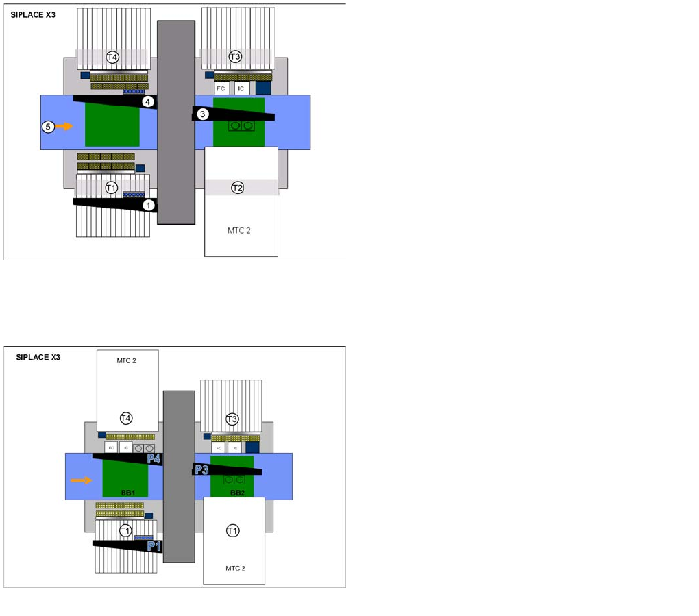
SIPLACE X3 with 1 MTC2 - Configu ration
3.1.2.3 SIPLACE X3 with 1 MTC2 - Configuration
SIPLACE X3 wi th 2 MTC2 - Co nfiguration Optio ns
3.1.2.4 SIPLACE X3 with 2 MTC2 - Configuration Options
SIPLACE X3 configuration options
Legend
▪ Dimensions (L x W) 2.38 x 2.75 m
▪ 1, 3, 4: Gantry 1, 3, 4
Gantry 1 and 4 with CPP, C&P20A or Twin Head
Gantry 3 with CPP or Twin Head
▪ T1 - T4: Locaton 1 - 4
Location 1, 3, 4: 40 tracks for 8 mm X feeder
Location 2: Changeover table or MTC2
▪ 5: Direction of transport , PCB conveyor with 5 areas
SIPLACE X3 configuration options
Legend
▪ Dimensions (L x W) 2.38 x 2.75 m
▪ 1, 3, 4: Gantry 1, 3, 4
Gantry 1 and 4 with CPP or Twin Head
Gantry 3 with CPP or Twin Head
▪ T1 - T4: Locaton 1 - 4
Location 1, 3, 4: 40 tracks for 8 mm X feeder
Location 2: Changeover table or MTC2
▪ 5: Direction of transport , PCB conveyor with 5 areas
Overview
Configurations SIPLACE X Series
Student Guide SIPLACE X-Serie and X4I SW70x (AL2) 48
SIPLACE X2 Conf iguration
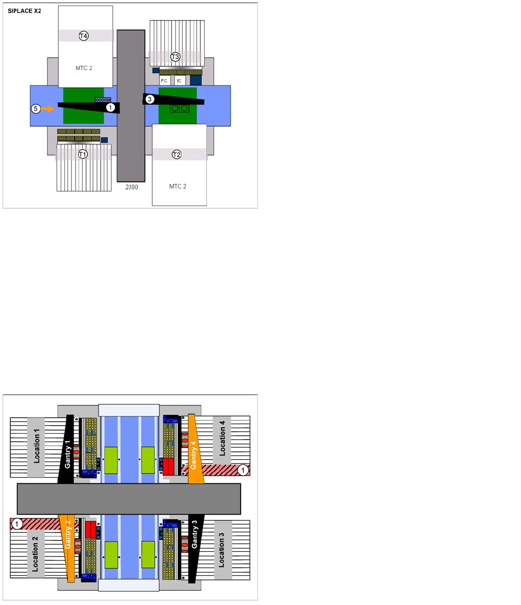
3.1.2.5 SIPLACE X2 Configuration
SIPLACE X4I - Co nfiguration
3.1.2.6 SIPLACE X4I - Configuration
The machine is designed and configured for the best possible placement performance. The standard
configuration therefore has 4 gantries, each with one C&P20A placement head. Travel range
optimization has been achieved by rotating gantries 2 and 4. This also enables both gantries to work
independently of one another in the same placement area: I-placement mode.
The following options can be used to further reduce the cycle time in the placement line:
▪ The combined PCB function
▪ A third conveyor lane with shuttle, to replace the productivity lift
▪ A conveyor with 4 lanes (quad lane)
SIPLACE X2 configuration options
Legend
▪ 1, 3: Gantry 1, 3
Gantry 1 with CPP, C&P20A or Twin Head
Gantry 3 with CPP, C&P20A or Twin Head
▪ T1 - T4: Locaton 1 - 4
Location 1, 3: 40 tracks for 8 mm X feeder
Location 2, 4: Changeover table or MTC2
▪ 5: Direction of transport , PCB conveyor with 5 areas
Placement area 2 is always equipped with one placement
head which can place higher components than
placement area 1.
Legend
1. Prohibited areas
Due to the rotated gantries 2 and 4, the marked areas
can not be reached. This applies with both C&P20A
and CPP head configurations.